An assignment for the course FLIGHT DYNAMICS AND AEROELASTICITY OF ROTARY-WING AIRCRAFT of Politecnico di Milano
'polarPcolor' function thanks to the contribution of @ECheynet, polarPcolor github page.
Qiuyang Xia
In this report, blade element momentum theory is briefly introduced. Momentum theory is utilized to first determine the inflow distribution of the rotor during a forward flight scenario, and then blade element analysis is used to calculate the thrust coefficient of each blade element. The reference blade airfoil is NACA0012, and the blade parameters and flight configurations are taken from a NASA experiment conducted in 1988. Several different inflow models tested in this report including uniform inflow model and various linear inflow model. Results showed the thrust coefficient distribution varies in terms of different inflow model, but correspond to a similar trend.
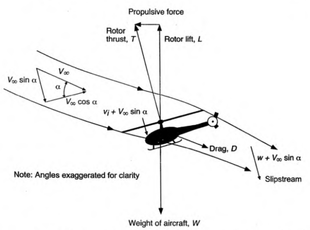
During forward flight, the rotor disk is tilted forward by an angle
Figure 1. Glauert's flow model for the momentum analysis of a rotor in forward flight.
where
Glauert made the hypothesis of mass inflow:
where
With the conservation of momentum, we can get:
From the energy conservation, we can get:
From which we can get the relationship between
Thus, total thrust can be expressed as follows:
Since hovering induced velocity can be expressed as:
the induced velocity can be expressed as:
Defining the advance ratio and the inflow ratio in forward flight as
From the equations above, the induced inflow ratio can be expressed as:
Thus, we get an implicit expression of inflow ratio:
In-flight experimental observations at higher advancing speed
(
In this equation,
Various researchers suggested different value couples for the coefficients in the linear inflow model, which is summarized in Table 1.
Table 1. Various Estimated Values of First Harmonic Inflow
| Author(s) | ||
|---|---|---|
| Coleman et al. (1945) | ||
| Drees (1949) | ||
| Payne (1959) | ||
| White & Blake (1979) | ||
| Pitt & Peters (1981) | ||
| Howlett (1981) |
A few blade element assumptions are made for the analysis. First, the aerodynamic characteristics of blade sections are independent. And second, the radial component of velocity does not affect lift an drag. Small angles assumption is also utilized in literature, but since the calculation in this report is conducted by PC, this assumption is neglected.
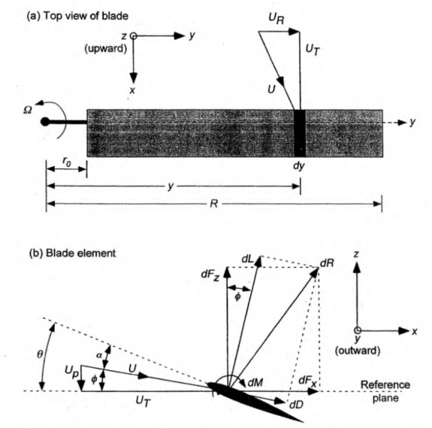
Figure 2 shows a typical blade element for analysis. The
Figure 2. Incident velocities and aerodynamic environment at a typical blade element.
and
Therefore, the resultant velocity at the blade element is:
The induced angle of attack, or the relative inflow angle
If the pitch angle at the blade element is
If the lift and drag coefficient is a function of effective angle of attack, they can be expressed as follows respectively:
Thus, the resultant incremental lift
where
Referring to Figure 2, the forces perpendicular and parallel to the rotor disk can be resolved respectively as:
Therefore, the blade element contributions to the thrust, torque, and power of the rotor are:
where
For conveniently analyze, the non-dimensional quantities are introduced as follows:
where
The formation of tip vortices produces large inflow and local lift
reduction which can be accounted for by either defining a simple ratio
factor, or by computing tip-loss effects based on a method devised by
Prandtl. The tip-loss factor derived by Prandtl can be expressed by
where
and the
The rotor and blade characteristics and performance parameters are taken from an experiment conducted by NASA in 1988, the experiment report was written by Elliott et al.
Table 2. Rotor and blade characteristics
| Characteristics | Symbol | Value |
|---|---|---|
| Number of blades | 4 | |
| Airfoil | NACA0012, |
|
| Hinge offset | 0.0508 m | |
| Root cutout | 0.2096 m | |
| Pitch-flap coupling | 0 | |
| Linear twist | -8 deg | |
| Radius | 0.8606 m | |
| Root chord | 0.0660 m |
Table 3. Rotor performance parameters
| Parameters | Symbol | Value |
|---|---|---|
| Drag coefficient | 0.0002 | |
| Shaft tilt angle | -3 deg | |
| Coning | 1.5 | |
| Infinite inflow ratio | 0.149 | |
| Thrust coefficient | 0.0063 | |
| Infinite inflow velocity | 28.5002 m/s | |
| Blade tip velocity | 190.2866 m/s |
It's worth noticing that the NASA report nominated rotor control values:
In the report,
and
The linear twisted blade can be expressed as:
The rotor flapping in forward flight is commonly expressed as a first order harmonics:
However, in the NASA report, the flapping angle was set to constant with
a coning angle
Figure 3 plotted the measured data from the NASA report and the multiple inflow model mentioned in the previous section. It is worth noticing that the positive direction defined by the NASA report is vertical to the rotor disk plane upwards, which is the opposite to the inflow models. Thus, the NASA data plotted in Figure 3 is multiplied by -1 to correspond to the inflow models.
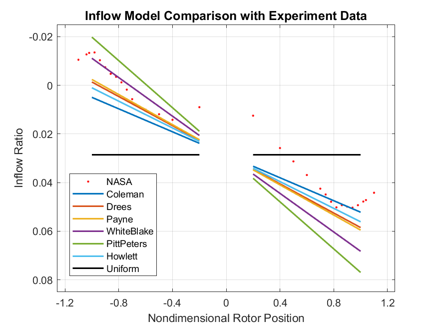
a) Inflow in longitudinal 0° - 180° direction, positive 0°.
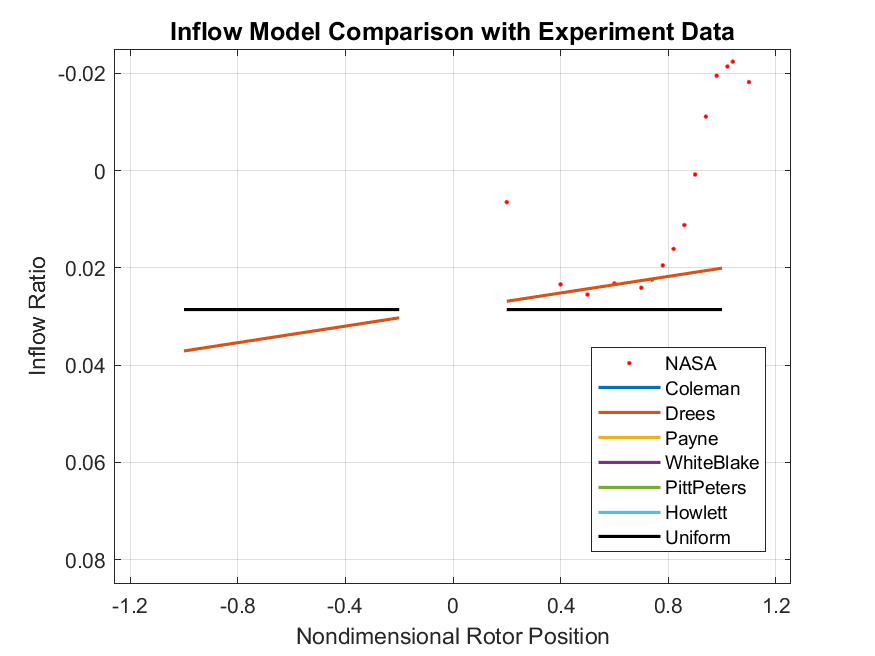
b) Inflow in lateral 90° - 270° direction, positive 90°, missing data for 270° direction in NASA measurement.
Figure 3. Measured and modeled inflow ratio at
From Figure 3 we can observe that the Coleman linear inflow model had
the most gentle slope in the longitudinal direction, while the Pitt &
Peters linear inflow model had the most aggressive slope. This was the
result of their choosing in the
Regarding to the lateral direction, since the above mentioned model all
assumed that
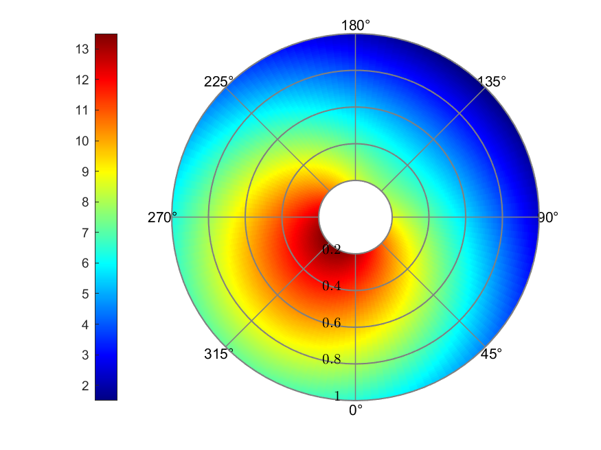
Due to the pitch control configurations, the theta value across the blade span and azimuth angle differs in each position. Figure 4 showed the corresponding theta value in each position in degrees.
Figure 4. Theta Configuration (deg)
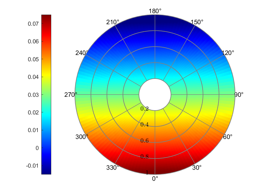
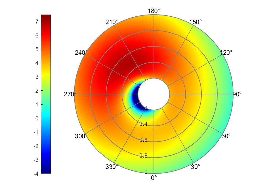
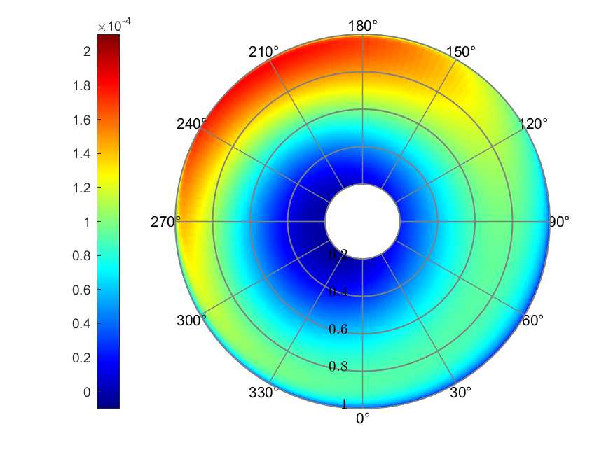
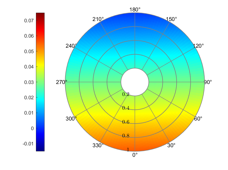
In this section, the distribution of inflow ratio, effective angle of attack (AoA), and thrust coefficient among the blade span and azimuth position is plotted. Also, define the "rotor balancing ratio" as:
which evaluates the thrust balancing of advancing side and retreating side of the rotor.
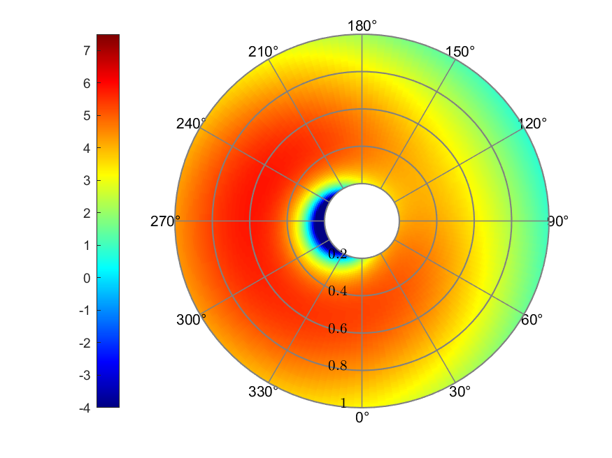
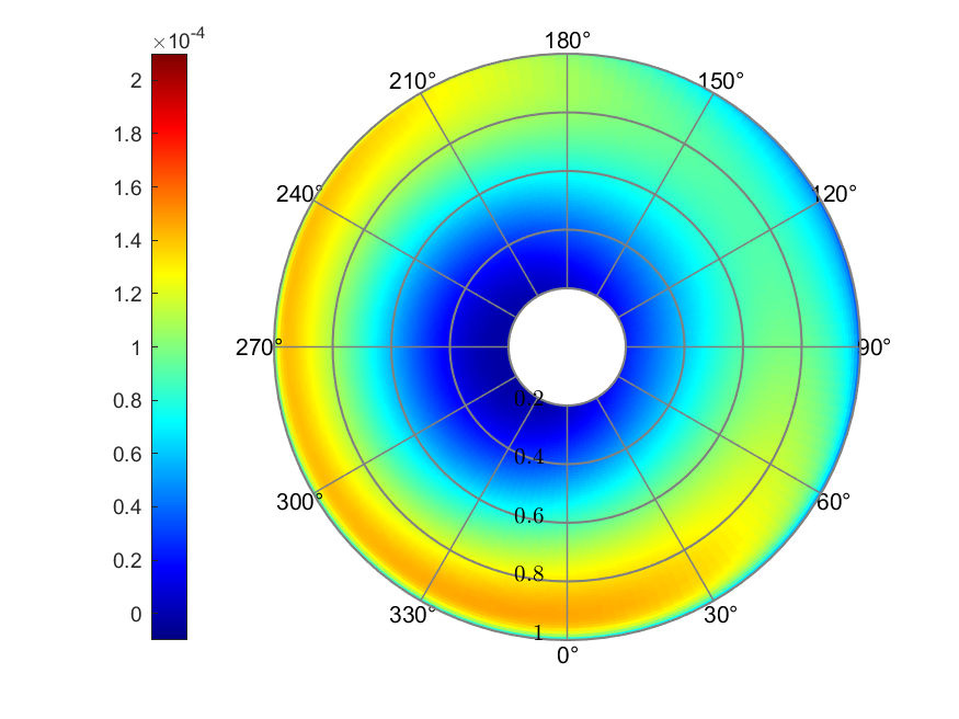
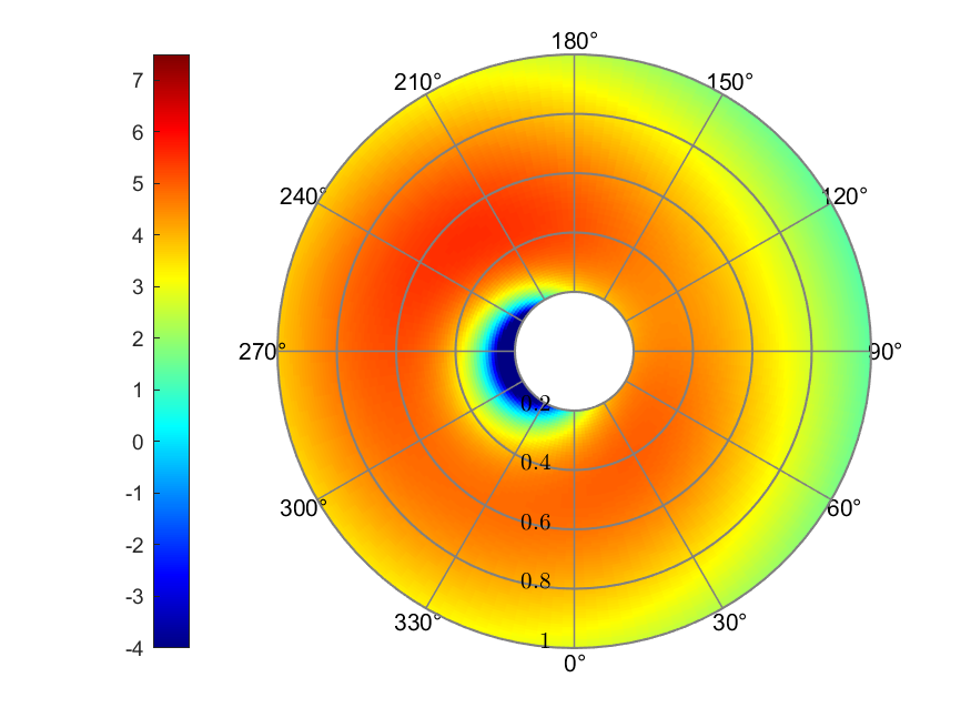
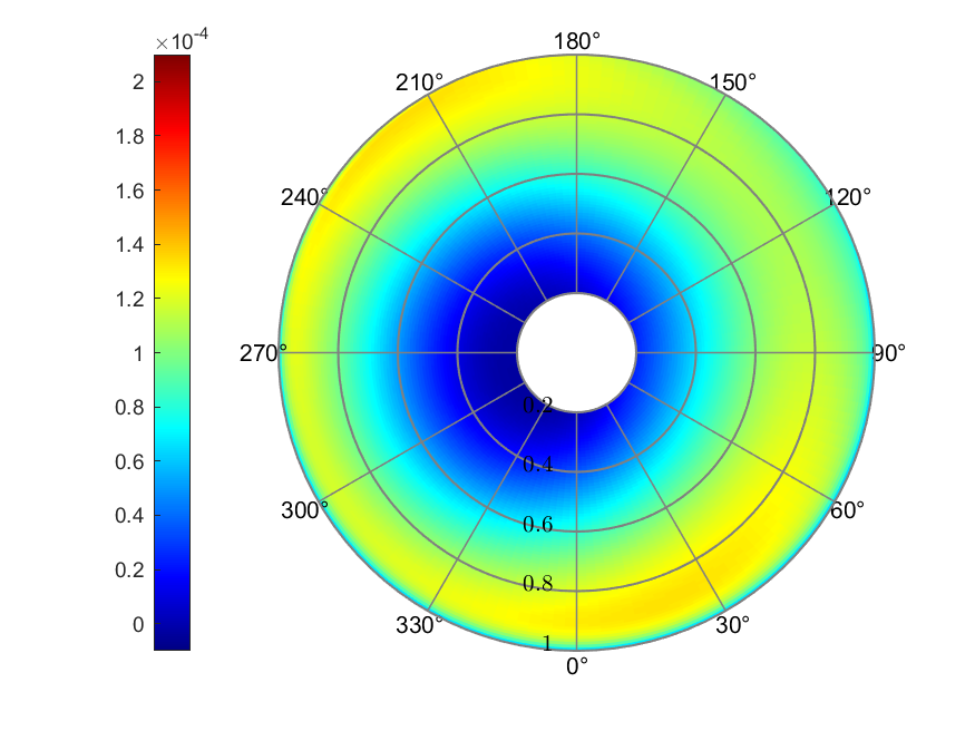
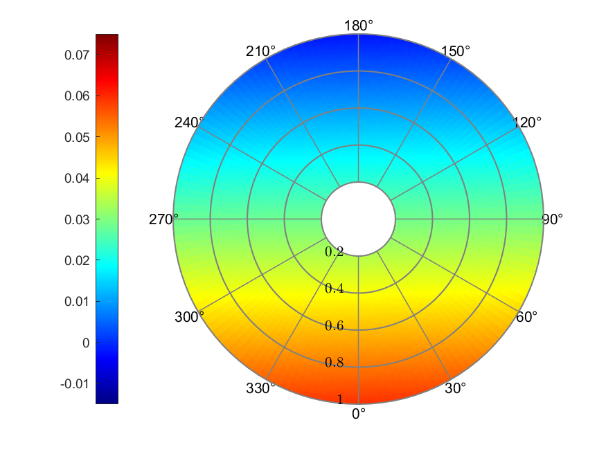
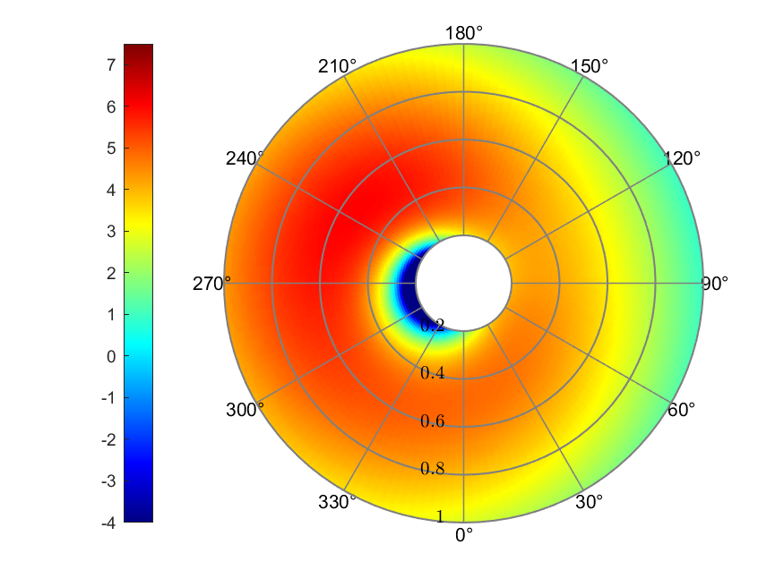
From Figure 5 to Figure 11, different inflow models were presented. But we can acquire some mutual phenomenon among them. The reverse flow region was around 0° to 180° of azimuth position within the blade span of 0.4, where the thrust coefficient also displayed the minimum value. The largest value of thrust coefficient always appeared near the blade tip position, although the azimuth position may differ.
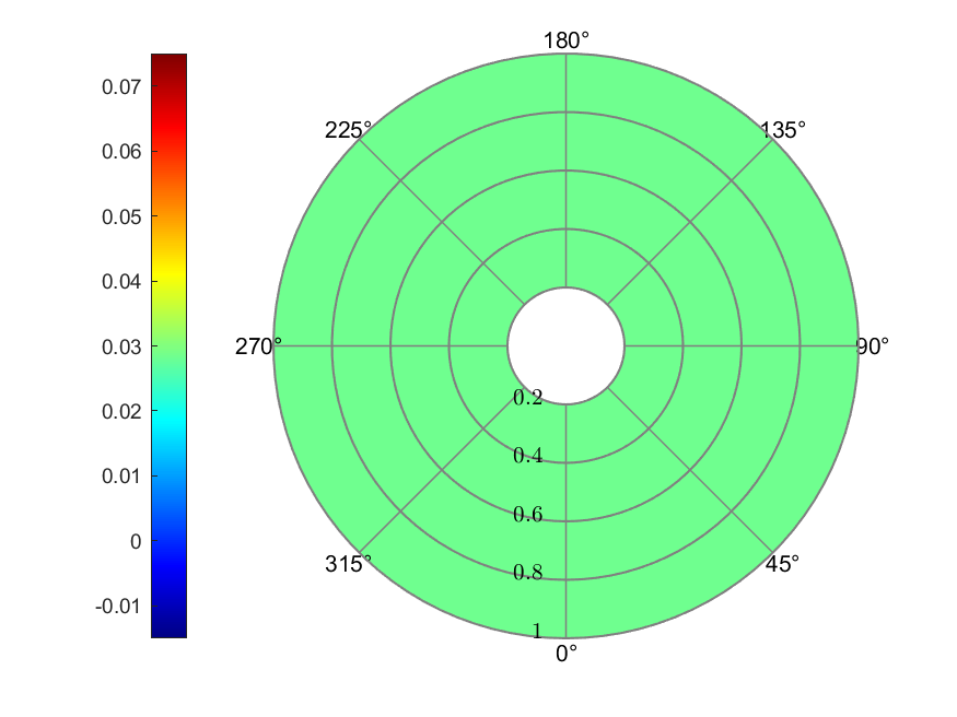
a) Inflow
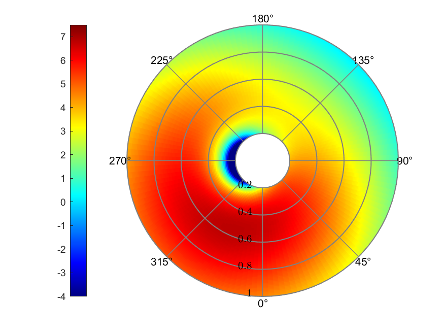
b) Effective AoA (deg)
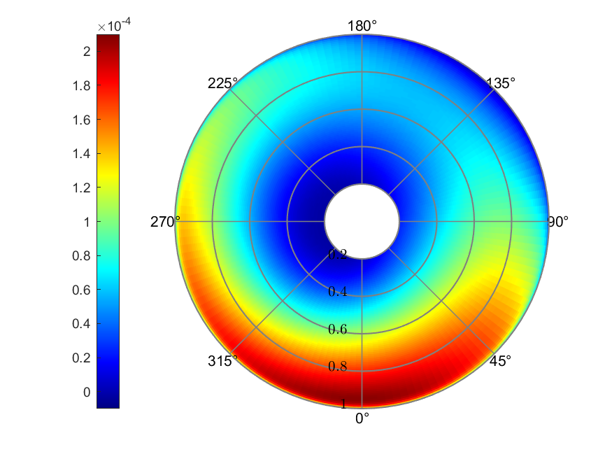
c) Thrust coefficient
Figure 5. Uniform inflow
The uniform inflow model had a inflow ratio of 0.0286 across the rotor.
The angle of attack ranged from -16.64° to 6.80°. The maximum Thrust
coefficient was
a) Inflow
b) Effective AoA (deg)
c) Thrust coefficient
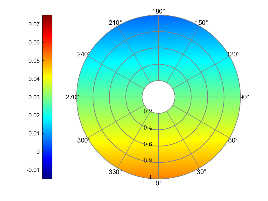
Figure 6. Coleman linear inflow
The Coleman linear inflow model resulted in a linear distributed inflow
ratio, ranging from 0.0050 to 0.0522. The maximum effective AoA was
5.82°, the minimum was -16.83°. Thrust coefficient presented its largest
value around 0° of azimuth position with a value of
a) Inflow
b) Effective AoA (deg)
c) Thrust coefficient
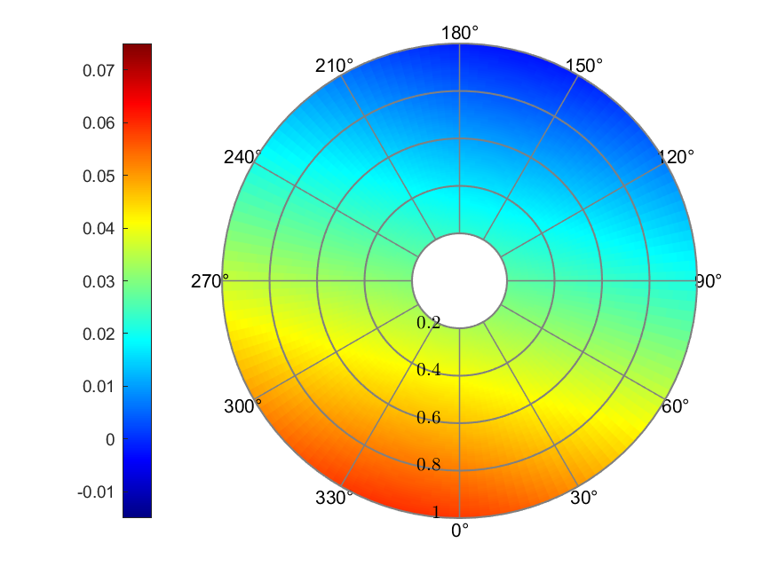
Figure 7. Drees linear inflow
The Drees linear inflow model was asymmetric to either axes, with a
minimum value of -0.0025 and a maximum value of 0.0597. The effective
AoA ranged from -18.32° to 5.54°. The maximum thrust coefficient value
appeared around both 30° and 210°, with values of around
a) Inflow
b) Effective AoA (deg)
c) Thrust coefficient
Figure 8. Payne linear inflow
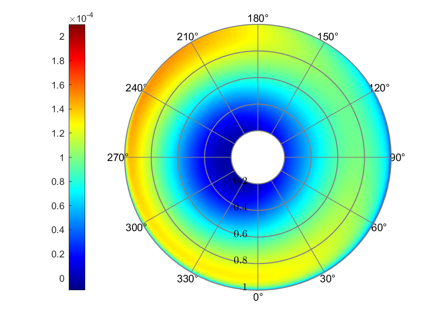
The Payne linear inflow model resulted in a linear distributed inflow
ratio ranging from -0.0024 to 0.0595. The effective AoA ranged from
-16.94° to 6.06°. The maximum value of thrust coefficient,
a) Inflow
b) Effective AoA (deg)
c) Thrust coefficient
Figure 9. White & Blake linear inflow
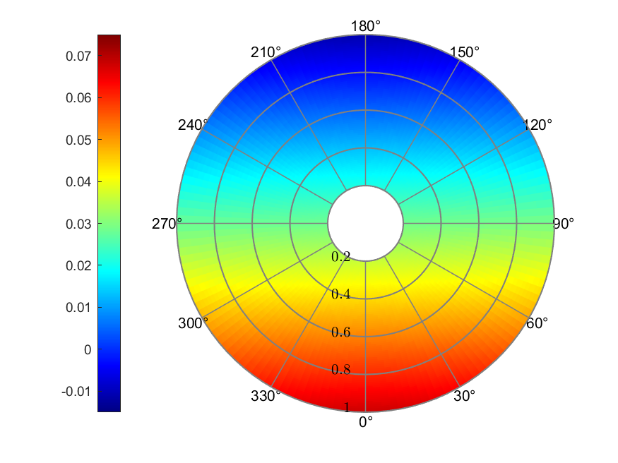
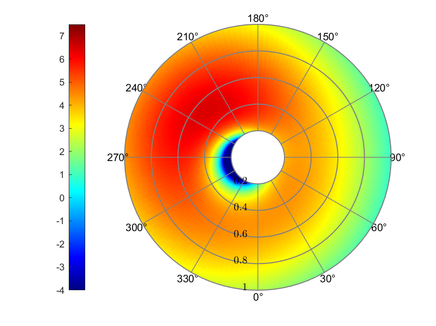
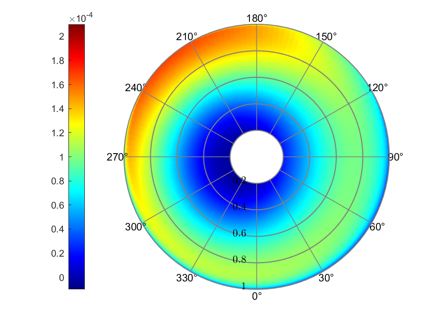
The White & Blake linear inflow model gave the inflow ratio ranging from
-0.0111 to 0.0683. The maximum AoA was 6.47°, and the minimum was
-17.07°. Thrust coefficient presented its largest value of
a) Inflow
b) Effective AoA (deg)
c) Thrust coefficient
Figure 10. Pitt & Peters linear inflow
The Pitt & Peters linear inflow model presented the largest range of
inflow prediction, with a minimum value of -0.0198 and a maximum value
of 0.0770. The effective AoA ranged from -17.26° to 6.93°, which also
was the largest range. The maximum value of thrust coefficient was
around
a) Inflow
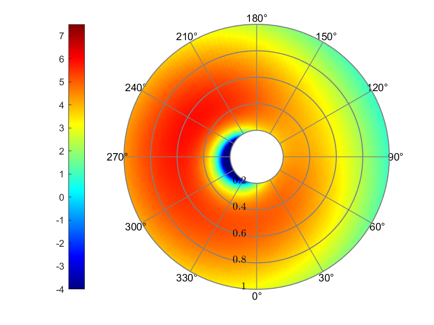
b) Effective AoA (deg)
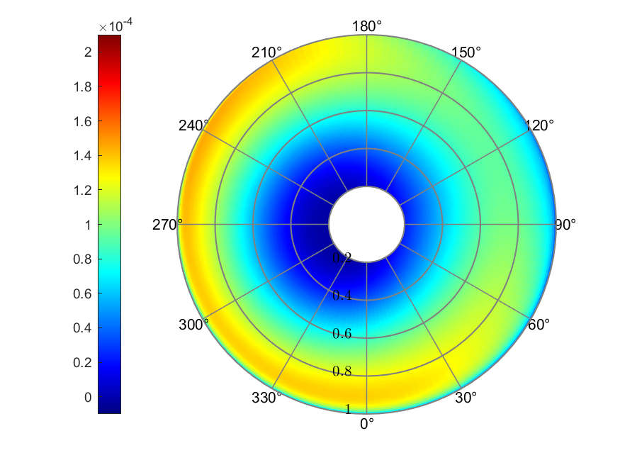
c) Thrust coefficient
Figure 11. Howlett linear inflow
The Howlett linear inflow model resulted in inflow ratio ranging from
0.0010 to 0.0561. The effective AoA ranged from -16.89° to 5.93°. The
thrust coefficient showed its larger value at the blade tip of
retreating side, with a maximum value of
This report briefly introduced blade element momentum theory in a forward flight scenario. Experiment conducted by NASA, Elliott et al in 1988 and the report were used as a reference for the numerical calculation of the BEM theory, although the pitch control was derived from another literature referring to the NASA report. Results showed that different inflow models had a similar trend in estimating the inflow ratio, but differed in specific parameter set. Resulted thrust coefficient had different kinds of distribution, but also had similar trend. The adjusted pitch control configuration showed better correlation with the experiment data.
-
Elliott J W, Althoff S L, Sailey R H. Inflow measurements made with a laser velocimeter on a helicopter model in forward flight. Volume 1: Rectangular Planform Blades at an Advance Ration of 0.15[R]. 1988.
-
Güner F. Comparison of rotor inflow models for flight simulation fidelity[D]. Middle East Technical University, 2016.
-
Pitt D M, Peters D A. Theoretical prediction of dynamic-inflow derivatives[J]. 1980.
-
Leishman G J. Principles of helicopter aerodynamics[M]. Cambridge University Press, 2006.
