
The eek! Is a 36 key per key RGB keyboard with a 90 degree split layout suited for travel and typing close to the body. It uses a Pro Micro, an Elite C, or a nice! nano and can be soldered low profile using castilated pads. The PCB can be flipped so that the silk is on top and the USB plugin can face to the right or left by using one of the following commands:
make eek:[keymap] or make eek/silk_up:[keymap]
The keyboard is compatible with MX, Alps, and Choc style switches. It can use SMD or through hole diodes. The per key RGB LEDs used in the build are the SK6812 Mini E (these can also be flipped for either side of the board). The eek! can be used without a case if you choose for a very low profile keyboard.
In the Case_Files folder, you will find the .svg and .dxf files to make your own case if you like.
In the QMK_Files folder, I've placed the needed qmk keyboard folder. Alternatively, you will find the eek! firmware on the main branch of QMK: QMK Firmware. Both have a basic keymap and a LED test keymap to make it easier to test your led soldering.
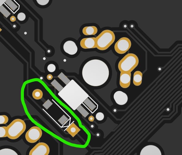
The eek! follows the normal rules when assembling the board. Below is an example of how the diodes, LEDs, and MX switches should be soldered. Keep in mind that if you flip the board to show the bat and eek! silk up, these same rules apply.

The footprints for the diodes have a small arrow indicating whitch direction the black line (or white line with SMD diodes).
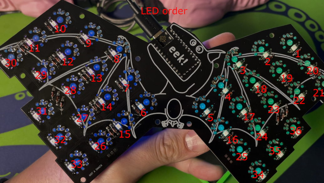
The LED order is below. Like Christmas lights, if you have a problem with one of the LEDs all of the LEDs after will not work. Keep in mind that this order is the same if they face silk up or silk down on the pcb.
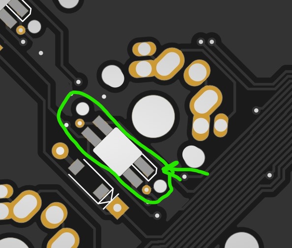
The SK6812 MINI E (be sure to get the "E" type) have one leg that has a clipped angle. That angled leg should be placed on the pad with the outline.
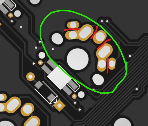
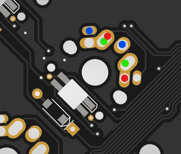
The eek! is compatible with MX, ALPs, and Choc style switches. In the first image below, be careful not to bridge solder across the red lines. Depending on your configuration, you may connect the column and rows so that the switch always appears to be pressed. This will cause strange problems. In the second image below, the colored dots represent the switch legs in the footprint: Red for MX, Green for ALPs, Blue for Choc.
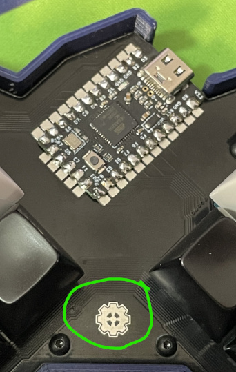
The Pro Micro (or compatible) should be soldered to the pcb on the side with the gear logo as seen in the picture below. If you are using a variant with castilated holes, the pads on eek! support soldering the Pro Micro on that way for a low profile build. Regardless if you decide to have the pcb flipped or not, the pro micro should be installed the same way.
I recommend flashing firmware on the pro micro before soldering to make sure that it's working properly.
Once you have your build environment set up using the guide in the QMK Documentation I recommend flashing the eek! with the default keymap or the ledtest keymap to make sure that everything is soldered correctly.
QMK firmware github is here.
QMK eek specific will be here.
If you made the eek! with the bat silk side down use the command:
make eek:default
If you made the eek! with the bat silk side up use the command:
make eek/silk_up:default
Additionally there is the possibilty of using the eek! wireless. If you have a nice!nano or another ZMK firmware compatible board, you can use eek! as shield. A basic keymap has been implemented. It is not recommended to use LEDs with a bluetooth board as they draw power, even when they're not on and limit the battery life drastically. The shield files can be found here. For more information on the zmk firmware refer to their website.
Disclaimer: Though it may be tempting, eek! is not a snack.