Legacy version supporting Raspian versions stretch and buster
Development of this version is discontinued; for latest developments see the PhyPiDAQ repository.
This is the English version of the documentation.
For German readers:
Die deutsche Version dieses Dokuments findet sich unter dem Link README_de.md bzw. README_de.pdf .
Aktuelle Präsentationen zur Projekt PhyPiDAQ: http://ekpwww.etp.kit.edu/~quast/Projects/PhyPiDAQ/
This python3 code provides some basic functionality for data acquisition and visualization like data logger, bar-chart, XY- or oscilloscope display and data recording on disk.
In addition to the GPIO inputs/outputs of the Raspberry Pi, the analogue-to-digital converters ADS1115 and MCP3008 and PicoScope USB-oscilloscopes are supported as input devices for analogue data, as well as a number of digital sensors using protocols like I²C or SPI.
The package provides an abstraction layer for measurement devices and sensors connected to a Raspberry Pi. Dedicated classes for each device provide a simple, unified interface, containing only the methods init(<config_dictionary>), acquireData(buffer) and closeDevice(). Simple examples with minimalist code illustrate the usage. The graphical user interface phypi.py and the script run_phypi.py provide a configurable environment for more complex measurements.
Fig. 1: Visualisation of the time dependence of two signals connected to an ADC

After installation - see below - a number of unified classes for data acquisition, visualisation and recording is available from the sub-directory ./phypidaq.
Each supported device needs a specific configuration, which is read from configuration files in sub-directory ./config. The overall configuration is given in files of type .daq, specifying which devices and display modules to use, the readout rate, calibrations or analytical formulae to be applied to recorded data, or ranges and axis labels of the graphical output.
The graphical user interface phypi.py aids in the administration of the configuration options and can be used to start data acquisition. In this case, configurations and produced data files are stored in a dedicated sub-directory in $HOME/PhyPi. The sub-directory name is derived from a user-defined tag and the current date and time.
Data acquisition may also be started via the command line:
run_phypi.py <config_file_name>.daq
If no configuration file is given, the default PhyPiConf.daq is used.
The sub-directory ./examples contains a number of simple python scripts illustrating the usage of data acquisition and display modules with minimalist code.
For many typical measurement tasks, preamplifiers are used to adjust the impedance (e.g. electrometer amplifier), to adjust the range levels or to amplify small signals in the µV range. A suggestion for the
simple implementation of such circuits is documented in the Hardware / directory.
The script run_phypi.py allows users to perform very general measurement tasks without the need to write custom code. The options for configuration of input devices and their channels as well as for the display and data storage modules are specified in a global configuration file of type .daq (in yaml markup language), which contains references to device configuration files of type .yaml.
A typical, commented example of the main configuration file is shown below. Note that text following a ''#''-sign is ignored and contains descriptive comments or alternatives.
file PhyPiConf.daq
# -- Configuration Options for PhyPiDAQ
# --------------------------------------

#
# -- configuration files for hardware devices
#
DeviceFile: config/ADS1115Config.yaml    # 16 bit ADC, I2C bus
# optional:
#DeviceFile: config/MCP3008Config.yaml   # 10 bit ADC, SPI bus
#DeviceFile: config/MCP3208Config.yaml   # 12 bit ADC, SPI bus
#DeviceFile: config/groveADCConfig.yaml  # 12 bit ADC on grove RPI shield
#DeviceFile: config/PSConfig.yaml        # PicoTechnology USB scope
#DeviceFile: config/MAX31865Config.yaml  # Pt 100 sensor
#DeviceFile: config/GPIOCount.yaml       # frequency count
#DeviceFile: config/DS18B20Config.yaml   # digital temperature sensor
#DeviceFile: config/MAX31855Config.yaml  # thermo element
#DeviceFile: config/BMP180Config.yaml    # pressure/temperature sensor
#DeviceFile: config/INA219Config.yaml    # Voltage/Current sensor
#DeviceFile: config/MMA845xConfig.yaml   # Accelerometer
#DeviceFile: config/VL53LxConfig.yaml    # ToF distance sensor

## an example of multiple devices
#DeviceFile: [config/ADS1115Config.yaml, config/GPIOCount.yaml]

# Demo options:
#DeviceFile: ToyDataConfig.yaml          # simulated data
#DeviceFile: config/ReplayConfig.yaml    # data from File

#
# -- configuration options for Channels
#
ChanLabels: [U, U]                 # names for channels
ChanUnits: [V, V]                  # units for channels
ChanColors: [darkblue, sienna]     # channel colours in display

# eventually overwrite Channel Limits obtained from device config
##ChanLimits:
## - [0., 1.]   # chan 0
## - [0., 1.]   # chan 1
## - [0., 1.]   # chan 2

# calibration of channel values
#  - null    or  - <factor> or  - [ [ <true values> ], [ <raw values> ] ]
#ChanCalib:
#  - 1.                       # chan0: simple calibration factor
#  - [ [0.,1.], [0., 1.] ]    # chan1: interpolation: [true]([<raw>] )
#  - null                     # chan2: no calibration

# apply formulae to (calibrated) channel values
#ChanFormula:
#  - c0 + c1  # chan0
#  - c1          # chan1
#  - null        # chan2 : no formula

#
# -- configuration options for graphical display
#
Interval: 0.1                # logging interval
#NHistoryPoints: 120          # number of points used in history buffer
DisplayModule: DataLogger    # history of channel signals
#DisplayModule: DataGraphs    # text, bar-graph, history and xy-view
#DisplayModule: null          # no graphical display
#Title: Demo                  # display title
#XYmode:     false            # enable/disable XY-display
## if more than two channels active:
#Chan2Axes: [0, 1, 0]         # assign channels to axes
#xyPlots:                     # define which axes to show
# - [0, 1]                    #  in xy-plot
# - [0, 2]
# - [1, 2]

#
# -- start in running or paused mode
# startActive: true  # start in running mode

#
# -- configuration options for output to file
#
#DataFile:   testfile.csv     # file name for output file,
DataFile:   null              #  null to disable
#CSVseparator: ';'            # field separator, set to ';' for German Excel

# enable buffering of latest data (depth NHistoryPoints from above)
#bufferData: PhyPiData    # file name to track latest data and eventually
#bufferData: null         #  store them, or null to switch off

# enable output to fifo (a linux pipe) to send data to other processes
DAQfifo: null
#DAQfifo: PhyPiDAQ.fifoTypical, commented examples of device configurations are shown below. The device configuration file for the analogue-to-digital converter ADS1115 specifies the active channels, their ranges and single or differential operation modes.
file ADS1115Config.yaml
# example of a configuration file for ADC ADS1115

DAQModule: ADS1115Config    # phypidaq module to be loaded

ADCChannels: [0, 3]         # active ADC-Channels
                        # possible values: 0, 1, 2, 3
                        # when using differential mode:
                        #    -  0 = ADCChannel 0
                        #            minus ADCChannel 1
                        #    -  1 = ADCChannel 0
                        #            minus ADCChannel 3
                        #    -  2 = ADCChannel 1
                        #            minus ADCChannel 3
                        #    -  3 = ADCChannel 2
                        #            minus ADCChannel 3

DifModeChan: [true, true] # enable differential mode for Channels

Gain: [2/3, 2/3]          # programmable gain of ADC-Channel
                          #   possible values for Gain:
                          #     - 2/3 = +/-6.144V
                          #     -   1 = +/-4.096V
                          #     -   2 = +/-2.048V
                          #     -   4 = +/-1.024V
                          #     -   8 = +/-0.512V
                          #     -  16 = +/-0.256V
sampleRate: 860           # programmable Sample Rate of ADS1115
                          #    possible values for SampleRate:
                          #    8, 16, 32, 64, 128, 250, 475, 860
The USB-oscilloscope PicoScope can also be used as data logger. In this case the average of a large number of measurements at high rate is taken. Choosing a measurement time of 20 ms very effectively eliminates 50 Hz noise.
file PSconfig.yaml
# example of a configuration file for PicoScope 2000 Series

DAQModule: PSConfig

PSmodel: 2000a

# channel configuration
picoChannels: [A, B]
ChanRanges: [2., 2.]
ChanOffsets: [-1.95, -1.95]
ChanModes: [DC, DC]
sampleTime: 2.0E-02
Nsamples: 100

# oscilloscope trigger
trgActive: false  # true to activate
trgChan: A
#trgThr: 0.1
#pretrig: 0.05
#trgTyp: Rising
#trgTO: 1000  # time-out

# internal signal generator
# frqSG: 100.E+3 # put 0. do disable
frqSG: 0.
Examples of other devices like the analog-to-digital converter MCP3008, of rate measurements via the GPIO pins of the Raspberry Pi or temperature measurements with the 1-wire digital thermometer DS18B20, PT100 sensors and the resistance-to-digital converter MAX31865 or thermocouples and the thermocouple-to-digital converter MAX31855 are also contained in the configuration directory, see files MCP3008Config.yaml, GPIOcount.yaml, DS18B20Config.yaml , MAX31865Config.yaml or MAX31855Config.yaml, respectively.
Get PhyPiDAQ code and dependencies
After setting up your Raspberry pi with the most recent version of the Debian Release stretch, enter the following commands in the console window:
mkdir git
cd git
git clone https://github.com/GuenterQuast/PhyPiDAQ
For your convenience, the script installlibs.sh installs all components needed for PhyPiDAQ. Simply execute
the script installlibs.sh once on the command line (without text after #):
cd ~/git/PhyPiDAQ  # change to installation directory
git pull           # eventually update to latest version of PhyPiDAQ
./installlibs.sh
The installation is now done and PhyPiDAQ is ready to be used.
The last part of the inatallation procedure is also valid to update an exiting verion of PhyPiDAQ .
To test the installaion without connected hardware or on a system other than the Raspberry Pi, PhyPiDAQ may be started in demo-mode:
cd ~/git/PhyPiDAQ  # change to installation directory
./run_phypi.py     # execute run_phypi.py with configuration PhyPiDemo.daq
Anmerkung
Remark
PhyPiDAQ is meant to be an educational tool. Confronting students with the full contents of this package is therefore not appropriate. Instead, it is recommended to create a working directory and copy examples from there to the student's working directory. This is achieved via the following commands:
# create PhyPi working directory and make examples and config files available
cd ~/git/PhyPiDAQ
./install_user.sh [<directory name>]
    # the input of a directory name is optional; default is "PhiPi"
# provide icon to graphical user interface
cp ~/git/PhyPiDAQ/phypi.desktop ~/Desktop
You might also consider moving the PhyPiDAQ package to system space, e.g. /usr/local:
sudo mv ~/git/PhyPiDAQ /usr/local/Please note that the paths in the example above must be adjusted in this case, e.g. ´~/git/` -> /usr/local/. The paths in ~/Desktop/phypi.desktop must also be changed appropriately. This is most easily achieved by right-clicking the icon and use the dialog "Properties".
The PhyPiDAQ package relies on code from other packages providing the drivers for the supported devices and libraries for data visualisation:
- the Adafruit Pyhon MCP3008 library
https://github.com/adafruit/Adafruit_Python_MCP3008 - the Adafruit Python ADX1x15 library
https://github.com/adafruit/Adafruit_Python_ADS1x15 - the Adafruit Python MAX31855 library
https://github.com/adafruit/Adafruit_Python_MAX31855 - the w1thermsensor library by Timo Furrer
https://github.com/timofurrer/w1thermsensor - components from the picoDAQ project
https://github.com/GuenterQuast/picoDAQ - the python bindings of the pico-python project by Colin O'Flynn
https://github.com/colinoflynn/pico-python - the low-level drivers contained in the Pico Technology Software Development Kit
https://labs.picotech.com/raspbian
For convenience, installation files for external packages and for modules of this package in pip wheel format are provided in sub-directory ./installlibs.
The visualization modules depend on matplotlib.pyplot, Tkinter and pyQt5, which must also be installed.
For completeness, the steps performed by the script installlibs.sh are documented here:
#
# script to install libraries PhyPiDAQ depends on
#
# -----------------------------------------------

sudo apt-get install python3-yaml
sudo apt-get install python3-scipy
sudo apt-get install python3-matplotlib
sudo apt-get install python3-pyqt5
sudo apt-get install libatlas-base-dev # needed to build nupmy

sudo pip3 install installlibs/whl/*.whl # python wheels

sudo pip3 install installlibs/tgz/*.tar.gz # python packages

sudo dpkg -i installlibs/picoscopelibs/*.deb # picoscope
sudo usermod -a -G tty pi # grant acces to USB for user pi- Open file /etc/apt/sources.list by
sudo nano /etc/apt/sources.list.
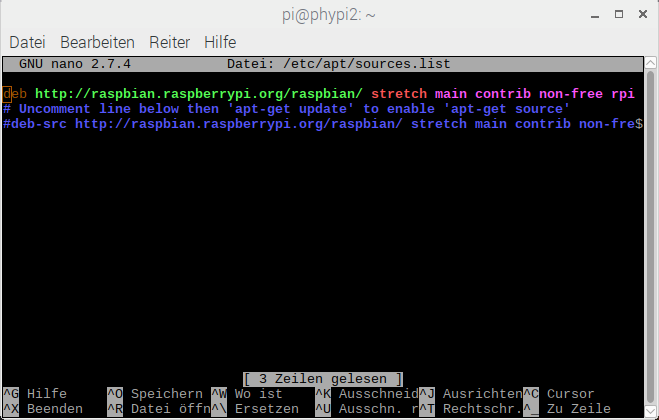
- Use arrow keys to navigate to the next free line and add entry
deb http://labs.picotech.com/raspbian/ picoscope mainto /etc/apt/sources.list.
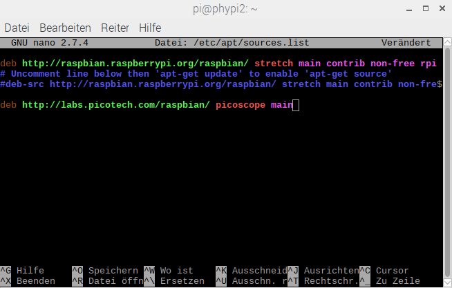
- Save file /etc/apt/sources.list by
Ctrl + OandEnter. - Close /etc/apt/sources.list by
Ctrl + X.


wget -O - http://labs.picotech.com/debian/dists/picoscope/Release.gpg.key | sudo apt-key add -
sudo apt-get update
sudo apt-get install libps2000
sudo apt-get install libps2000a

# allow access of user pi to usb port
sudo usermod -a -G tty pirun_phypi.py
run data acquisition and display modules as specified in configuration files (defaultPhyPiConf.daqand .yaml files ins subdirectory config/)phypi.py
graphical user interface to edit configuration files and start the scriptrun_phypi.py
-
phypidaq/__init__.py
initialisation for package phypidaq -
phypidaq/_version_info.py
version info for package phypidaq -
phypidaq/ADS1115Config.py
class for handling of analog-to-digital converter ADS1115 -
phypidaq/MCP3008Config.py
class analog-to-digital converter MCP3008 -
phypidaq/MCP3008Config.py
class for current and voltage sensor INA219 -
phypidaq/DS18B20Config.py
class for handling of digital thermometer DS18B20 -
phypidaq/BMPx80Config.py
class for the digital temperature and pressure sensors BMP180/280 or BME280 -
phypidaq/MMA8451Config.py
class for the digital accelerometer MMA8451 -
phypidaq/GPIOCount.py
class for reading rates from GPIO pins -
phypidaq/MAX31855Config.py
class for MAX31855 thermocouple-to-digital converter -
phypidaq/MAX31865Config.py
class for MAX31865 resistance-to-digital converter -
phypidaq/PSConfig.py
class for PicoScope USB oscilloscopes -
phypidaq/VL53LxConfig
class for VL53L1X distance sensor -
phypidaq/TCS34725Configclass for TCS34725 RGB color sensor -
phypidaq/AS7262Configclass for AS7262 six channel color sensor -
phypidaq/AS7265xConfigclass for AS7265x 18 channel spectral sensor -
phypidaq/GDK101Config.py
class for gamma ray detektor GDK101, FTLAB -
phypidaq/ToyDataConfig.py
class to generate simulated data (for test, debugging or exercises) -
phypidaq/ReplayConfig
class to replay data from file -
phypidaq/Display
interface and background-process handling data visualisation -
phypidaq/DataLogge
class for display of data histories and xy diagrams -
phypidaq/DataGraph
general display module for data as bar graphs, history plots and xy-graphs -
phypidaq/DataRecorde
store data in CSV format -
phypidaq/pulseGPIOclass to set or pulse GPIO pin of raspberry py -
phypidaq/runPhyPiDAQ
class for scriptrun_phypi.py -
phypidaq/runPhyPiUI.pyclass for graphical user interfacephypi.py, usesphypiUIas base class -
phypidaq/phypyUIbase class for
runPhyPyUI, generated fromphypi.uiwithpyuic5 -
phypidaq/phypi.uioutput ofdesigner-qt5, describes the graphical user interface
phypidaq.cfg
global configuration for directory with configuration files and inital work directory; if this file is found in thehomedirectory, it takes priority over the one in the installation directoryPhyPiConf.daq
main configuration file, depends on device configurations in sub-directory config/config/ADS1115Config.yaml16 bit ADCconfig/MCP3008Config.yaml10 bit ADCconfig/MCP3208Config.yaml12 bit ADCconfig/INA219Config.yamlcurrent and voltage sensoreconfig/DS18B20Config.yamldigital temperature sensorconfig/BMP280Config.yamltemperature and pressure sensor- ``config/BMP180Config.yaml` temperature and pressure sensor
config/GPIOCount.yamlfrequency measruement via GPIO pinconfig/MAX31855Config.yamlconverter for thermocoupleconfig/MAX31865Config.yamlconverter for PT-100config/INA219Config.yamlcurrent-voltage sensorconfig/TCS34752Config.yamlRGB sensorconfig/AS7262Config.yaml6 channel color sensorconfig/AS7265xConfig.yaml18 channel spectral sensorconfig/VL53L1XConfig.yamldistance sensorconfig/GDK101.yamlgamma-ray detectorconfig/PSConfig.yamlPicoScope usb oscilloscope
-
examples/read_analog.py
very minimalist example to read one channel from an analog-to-ditigal converter -
examples/display_analog.py
very minimalist example to read one channel from an analog-to-ditigal converter and display data as a history graph -
examples/display_analog2.py
read two channels from an analog-to-ditigal converter and display data as a history graph -
examples/read_INA210.py
read data from INA219 current and voltage sensor -
examples/read_18B20.pys simple example to read the temperature sensor DS18B20 -
examples/readBMPx80.pysimple example to read the digital temperature and pressure sensor BMP180/280 -
examples/readMMA8541.pysimple example to read the digital accelerometer MMA8451 -
examples/runOsci.py
run an oscilloscope display, configuration as specified in .yaml file (default isPSOsci.yaml) -
examples/GPIO-In-Out.py
example to control GPIO pins: generate square signal on output pin from variable voltage on input pin -
examples/poissonLED.py
generate a random signal following Poisson statistics on a GPIO pin -
examples/FreqGen.py
generate a fixed frequency signal on a GPIO pin -
examples/set_MPC4725
example to set voltage on MCP4725 ditital-to-analog converter
examples/Amperemeter.daq
display current and eventually voltage read from INA219 sensorexamples/Barometer.daq
uses BMB180 or BMP280 sensors to display temperature and air pressureexamples/Accelerometer.daq
uses MMA8451 to display x-, y- and z-accelerationexamples/NoiseMeter.daq
measure noise with a microphone connected to PicoScope USB oscilloscope; displays the rms of 200 samples taken over a time periods of 20 ms. Can also be used with geophone SM-24examples/RGBsensor.daqRGB color sensorexamples/ColorSpectrum.daqsix channel color sensorexamples/AS7265x.daq18 channel spectral sensorexamples/GammaDose.daq
measurement of gamma-ray dose with GDK101examples/ToyData.daqgeneration and display of simulated dataexamples/ReplayData.daq
data from file (for demo mode)examples/readPipe.py
read data from named linux pipe (run_phypi.py with option DAQfifo: <pipe name>)
doc/Kurs_digitale_Messwerterfassung_mit_PhyPiDAQ.md (.pdf)
German only: Introductory course to measuring with the Raspberry Pidoc/Einrichten_des_Raspberry_Pi.md (.pdf)
German only: setting up the Raspberry Pi for this projectdoc/Komponenten_fuer_PhyPi.md (.pdf)
recommended components for this projectdoc/Bauanleitung_Kraftsensor.md (.pdf)
building instructions for a force sensorHardware
documentation of card with analog preamplifiers- electrometer
- instrument amplifier
- level shifter
- ... and others