Drivers for the accelerometer ADXL345 for both I2C and SPI using the STM32 HAL.
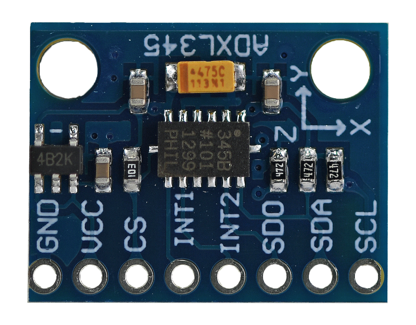
Most pre-made ADXL345 breakout boards follow the same pattern.
| Pin | Function | I2C | SPI |
|---|---|---|---|
| GND | Ground | ||
| VCC | Power Supply 3-6V | ||
| CS | Chip Select for SPI interface | For I2C it needs to be pulled low* | CS*** |
| INT1 | Interrupt 1 | ||
| INT2 | Interrupt 2 | ||
| SDO | Serial Data Output SPI/ALT ADD | If pulled HIGH -> I2C Addr 0x1D** | MISO |
| SDA | Serial Data for I2C interface | SDA | MOSI |
| SCL | Serial Clock for I2C interface | SCL | SCLK |
*By default most ADXL345 breakouts CS is already pulled low. This pin is negated.
**By default most ADXL345 breakout boards SDO is pulled low so its I2C adress is (0x53 << 1)
*** I couldn't get NSS STM32 pin to work, so I used a GPIOA Pin 4 pin to Chip Select the communications.
In the STMCube IDE initialize a I2C port with 100.000 KHz rate and wire the ADXL345.
MX_I2C2_Init();                           // In my case I'm initializing I2C port 2
ADXL345 adxl345;                          // Create an ADXL345 struct which will hold the internal variables
ADXL345_initialization(&hi2c2, &adxl345);  // Check that the ADXL345 has started correctly
...
while(1)
{
    ADXL345_get_acc_norm(&adxl345);         // Function to update the accelerometer values
    ADXL345_print_norm(&adxl345, &huart3);  // Print the values through the UART port
}In the STMCube IDE initialize a SPI port with a speed lower thatn 5 MBit/s and wire the ADXL345.
MX_SPI1_Init();                           // In my case I'm initializing SPI port 1
ADXL345 adxl345;                          // Create an ADXL345 struct which will hold the internal variables
ADXL345_initialization(&hspi1, &adxl345);  // Check that the ADXL345 has started correctly
...
while(1)
{
    ADXL345_get_acc_norm(&adxl345);         // Function to update the accelerometer values
    ADXL345_print_norm(&adxl345, &huart3);  // Print the values through the UART port
}The ADXL345 is connected to a STM32F412ZG board via I2C and it outputs its data through an UART port and controls the brightness of 3 LEDS according to its XYZ axis inclination.
