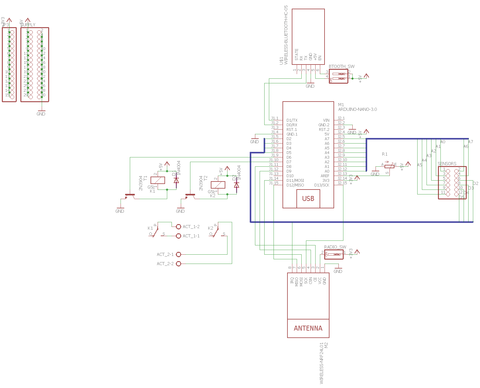
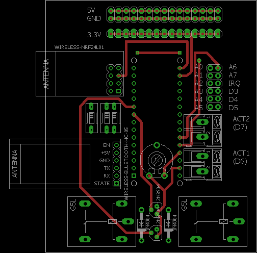
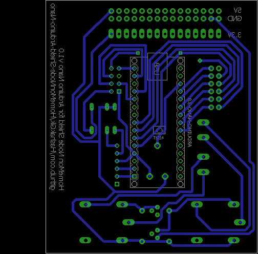
This Eagle layout can be used to etch a single HomeMon node, in the form of a shield for the Arduino Nano prototyping platform.
The Arduino Nano sketch for this shield is available here.
- Eleven pins can be used as general I/O (e.g. for reading data from sensors)
- Two actuators can be driven by relays
- A power supply bus (5V, 3.3V and ground lines) with fifteen pins is added for convenience
- An NRF24L01+ 2.4 GHz transceiver is used for inter-node communication, and serial communication (either via the USB converter of the Arduino or, optionally, via an HC-05 based Bluetooth adapter allows the node to be connected to a desktop sink running the HomeMon Viewer Application
- A trimmer can be used to set the analog voltage reference
- Both the 2.4 GHz transceiver and the optional Bluetooth adapter can be turned on/off by switches (the Bluetooth adapter can additionally be put into AT mode for configuration purposes).
- Serial pins (
D0andD1): Bluetooth adapter - SPI pins (
D11toD13),D2,D8andD9pins: radio transceiver - Analog pins (
A0toA7): directly connected to theSENSORSconnector - Digital pins
D2toD5: directly connected to theSENSORSconnector. (Important note: pinD2is also connected to theIRQpin of the transceiver) - Digital pins
D6andD7: connected to the actuator connectors (ACT1andACT2respectively) through two relays AREF: connected to the analog reference trimmerGND,3V3and5V: connected to the power supply connectorsRST,VINandD10: unconnected.
- 1x 10k linear trimmer
- 1x Arduino Nano
- 2x Diodes with DO-41 package (e.g. 1N4004)
- 1x DIP switch SPST 1 position (RS-Components code: 877-2100)
- 2x Monostable 5V DC G5LE relays (RS-Components code: 808-8465)
- 2x NPN transistors with TO-92 package (e.g. 2N3904)
- 1x NRF24L01+ module (8 pins breakout board)
- 2x Two-ways PCB terminal blocks with 5.08mm pitch (RS-Components code: 425-8720)
Optionally, for Bluetooth support:
- 1x DIP switch SPST 2 positions (RS-Components code: 877-2113)
- 1x HC-05 Bluetooth module (6 pins breakout board)
- The shield relies on the Arduino for power supply (i.e. it doesn't have batteries nor a DC connector, energy must be supplied from the USB connector or the
VINpin) - Arduino pin
D10 (SS)is left unconnected because the SPI library may malfunction if the pin is set to high when the Arduino is acting as SPI master - The additional components are defined in the freely available DIYmodules.org component library.


