AoCStream is a CNN processing accelerator that implements a whole CNN with on-chip memories (All-on-Chip implementation). The detailed architecture will be presented as a poster in ISFPGA 2023, and a full version paper is available on arXiv.
Please cite AAP in your publications if it helps your research:
@article{aocstream_2021,
	author = {Kang, Hyeong-Ju},
	title = {AoCStream: All-on-Chip CNN Accelerator With Stream-Based Line-Buffer Architecture},
	version = {1},
	date = {2011-12-19},
	eprinttype = {arxiv},
	eprintclass = {cs.LG, cs.GT},
	eprint = {http://arxiv.org/abs/1112.4344v1},
	url = {http://arxiv.org/abs/1112.4344v1}
}
@inproceedings{aocstream_isfpga,
	author = {Kang, Hyeong-Ju},
	title = {AoCStream: All-on-Chip CNN Accelerator With Stream-Based Line-Buffer Architecture},
	booktitle = {Proceedings of ACM/SIGDA International Symposium on Field Programmable Gate Arrays},
	year = {2023},
	pages = {}
}
Not board confirmed
| Input Size | LUT(K) | Reg(K) | BRAM | URAM | DSP | Clock(MHz) | FPS | Bit file |
|---|---|---|---|---|---|---|---|---|
| 320x320 | 137 | 218 | 454 | 25 | 464 | 428 | 260.9 | bit |
| 384x384 | 145 | 219 | 454 | 25 | 464 | 349 | 147.7 | bit |
| 448x448 | 148 | 233 | 476 | 25 | 476 | 400 | 124.5 | bit |
| 512x512 | 154 | 232 | 476 | 44 | 476 | 375 | 89.3 | bit |
The models can be downloaded at Section 2.1 of this page
Not board confirmed
| Input Size | LUT(K) | Reg(K) | BRAM | URAM | DSP | Clock(MHz) | FPS | Bit file |
|---|---|---|---|---|---|---|---|---|
| 320x320 | 156 | 195 | 445 | - | 360 | 186 | 100.9 | bit |
Board confirmed with the example host board on Applendix 2.
| Input Size | LUT(K) | Reg(K) | BRAM | URAM | DSP | Clock(MHz) | FPS | Bit file |
|---|---|---|---|---|---|---|---|---|
| 320x320 | 147 | 195 | 445 | - | 360 | 120 | 65.1 | bit |
The host sends image data with the following signals. In the figure, t_cyc means the clock cycle time of the CNN processing.

The in_data signal consists of 26 bits.
- in_data[25]: 1 - on the first pixel of a frame, 0 - o.w.
- in_data[24]: 1 - on the first pixel of a line, 0 - o.w.
- in_data[23:16]: Red
- in_data[15:8]: Blue
- in_data[7:0]: Green
The CNN processing board sends the detection results with the following signals. In the figure, t_cyc means the clock cycle time of the CNN processing.

The out_data signal consists of 16 bits.
| out_data[15:13] | out_data[12:0] |
|---|---|
| 000 | 7 bit class number (1~81) |
| 001 | 8 bit probalility (0.xxxxxxxx) |
| 010 | xmin |
| 011 | xmax |
| 100 | ymin |
| 101 | ymax |
The counting value out_data[15:13] increments 0 to 5 at the rising edge of in_strb. The remainig bits of out_data changes accordingly.
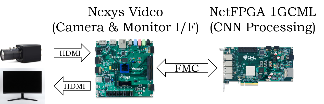
Nexys Video board is used for the example host board. The HDMI project of Nexy Video was modifed.
- Download the project. (For your information, FMC connection XDC)
- Make a system as follows.
- Run Nexys Video as instructed in the HDMI project.
- Program the CNN processing board with a bit file as in Section 1.2.1.
