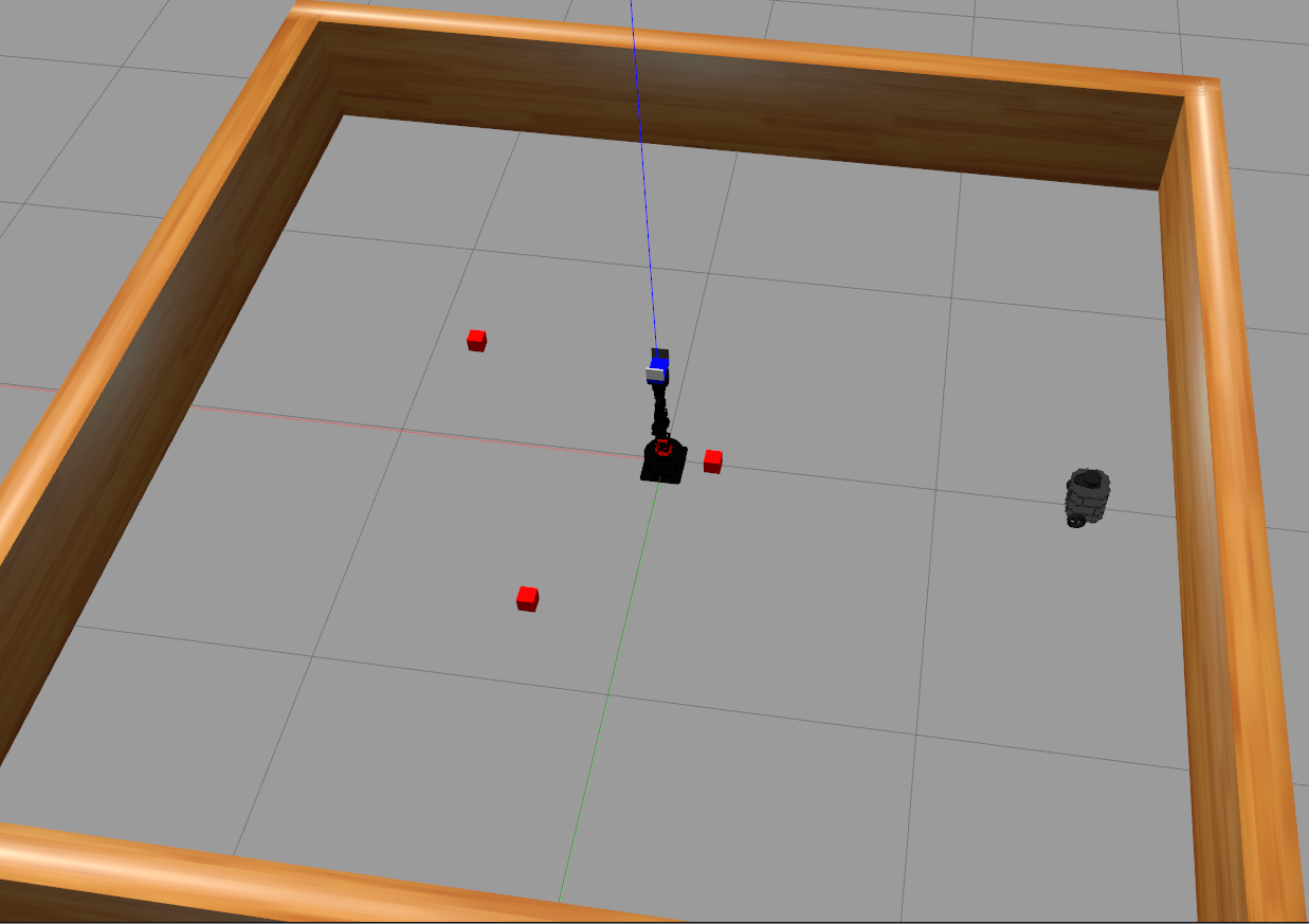
two robots, cyton_300_gamma and turtlebot3, achive a common goal
Cyton_300_gamma and Turtlebot3,need to Build pile of cudes
Itay Grinberg & Benjamin Barns
itaygrinberg@campus.technion.ac.il
- DOF Degrees Of Freedom
- ROS Robot Operating System
- ARC Amazon Robotics Challenge
- EE End-Effector
- WC Wrist Center
- DH Denavit–Hartenberg
- FK Forward Kinematics
- IK Inverse Kinematics
- RRR Revolute Revolute Revolute
- URDF Unified Robot Description Format
- TB3 Turtlebot3
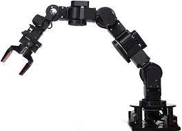
The proposed project focuses on heterogeneous teams of autonomous robots.This project originated from Cyton 300 gamma Robotic arm - Pick & Place project
which get assistnce from Turtlebot3 - Burger .
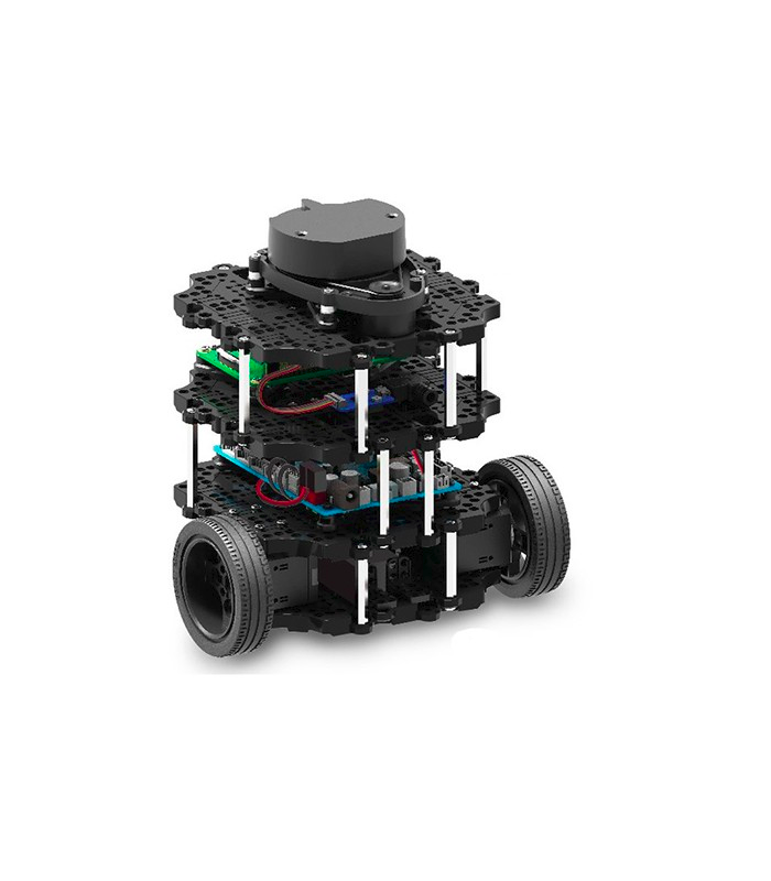
Fig. 1.2 A Turtlebot3 - Burger
In order to collaborate effectively, AI agents must be able to reason about the behaviors of other agents, learn to communicate effectively, learn to ask for help from other agents and understand how they can offer valuable assistance to other agents. .
The objective is to find methods that allow the robots to compute behaviors that maximize their `helpfulness' to other robots while complying with their own resources and objectives.
This is a challenging problem since it requires an online analysis of the current setting and the current capabilities of each agent, an online computation of an optimal policy for each agent, and a way for the agents to monitor and coordinate their progress.In addition, it requires an integration of high-level task planning and low-level motion planning in a multi-agent setting.
Within the context of this project, a single task cycle can be divided into the following tasks:
- Identify the target object on the area
- Plan and perform a clean movement towards the object
- Efficiently grasp/pick the target object without disturbing other objects
- Plan and perform a clean movement towards the drop-off site
- Efficiently stow/place the object at the drop-off site
- If possible back to 1. Else ask for help and countine.
- Plan and perform movement to the object the first agent can't reach
- attach the object
- Plan and perform a clean movement towards the pick-up point
- detach the object
- movefrom the area
Collaborative ability can be beneficial in several ways: Performing complex tasks that can't be done by one agent alone. Additionally, information sharing should occur and maximize the utilization of each agent's abilities, whether together or individually. Furthermore, when dealing with an environment involving people, we can define roles for the robot and the person.
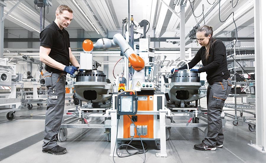
Fig. 1.3 industrial robots can operate in a collaborative environment
Robotic manipulators and Differential Drive Robot like Tb3 have become ubiquitous in almost every industry; from food, beverage, shipping and packaging to manufacturing, foundry and space:
- Palletizing food in a bakery
- Serving food
- Precision painting of automobiles and aircrafts
- Targeting products to their packaging stations in a warehouse
These jobs all require the same set of core capabilities, namely, the robotic arm's end-effector being able to reach specific coordinates within its workspace, and the TB3 can navigate to a point in the environment at the location.
The project uses ROS Melodic Morenia running on Ubuntu 18.04 LTS ( bionic beaver).
The following tools are used for simulation and motion planning:
- Gazebo: a physics based 3D simulator extensively used in the robotics world
- RViz: a 3D visualizer for sensor data analysis, and robot state visualization
- MoveIt!: a ROS based software framework for motion planning, kinematics and robot control
Once ROS is installed, we can proceed with the environment setup for the project:
1. Chack that you have the following dependencies and if not run the following commands:
sudo apt-get install ros-melodic-ros-controllerssudo apt-get install ros-melodic-gazebo*sudo apt-get install ros-melodic-moveit*sudo apt-get install ros-melodic-industrial-coresudo apt-get install ros-melodic-trac-ik-kinematics-pluginsudo apt-get install ros-melodic-joy ros-melodic-teleop-twist-joy \
ros-melodic-teleop-twist-keyboard ros-melodic-laser-proc \
ros-melodic-rgbd-launch ros-melodic-depthimage-to-laserscan \
ros-melodic-rosserial-arduino ros-melodic-rosserial-python \
ros-melodic-rosserial-server ros-melodic-rosserial-client \
ros-melodic-rosserial-msgs ros-melodic-amcl ros-melodic-map-server \
ros-melodic-move-base ros-melodic-urdf ros-melodic-xacro \
ros-melodic-compressed-image-transport ros-melodic-rqt* \
ros-melodic-gmapping ros-melodic-navigation ros-melodic-interactive-markers
2. Create a catkin workspace if haven't already
mkdir -p ~/catkin_ws/src
cd ~/catkin_ws/
catkin_init_workspace
ls -l
3. Clone or download project repository into the src directory of the catkin workspace
cd ~/catkin_ws/src
git clone https://github.com/andreasBihlmaier/gazebo2rviz.git
git clone https://github.com/andreasBihlmaier/pysdf.git
git clone https://github.com/JenniferBuehler/general-message-pkgs.git
git clone https://github.com/JenniferBuehler/gazebo-pkgs.git
git clone https://github.com/pal-robotics/gazebo_ros_link_attacher.git
git clone -b melodic-devel https://github.com/ROBOTIS-GIT/turtlebot3.git
git clone https://github.com/ItayGrinberg93/Multi_Agent_System_Based_Help.git
4. Build the project
cd ~/catkin_ws
catkin_make5. To use TB3 add to bash.rc or open two terminals and run in each:
source devel/setup.bash
export TURTLEBOT3_MODEL=burger
6. At the first terminal run:
roscore 7. At the secound terminal run:
roslaunch new_moveit_config multi_gazebo_update.launch 8. At the third terminal run:
roslaunch new_moveit_config bringup_update.launch
9. Open a new terminal and run:
cd ~/catkin_ws
source devel/setup.bash
cd src/py_moveit/scripts
chmod +x python_sim.py
rosrun py_moveit python_sim.pyThe following theoretical concepts are used in this project:
-
Generalized Coordinates and Degrees of Freedom
-
Common industrial serial manipulators and their workspace
-
Rotation matrices and composition of rotations
-
Euler angles and Euler theorem
-
Euler to Quaternions
-
Homogeneous transforms
- Denavit–Hartenberg parameters
- Forward and Inverse Kinematics
- Generalized Coordinates and Dynamic model
Serial manipulators are robots composed of an assembly of links connected by joints (a Kinematic Chain), and the most common types of robots in industry.
Generalized coordinates are parameters that are used to uniquely describe the instantaneous dynamical configuration of a rigid multi-body system relative to some reference configuration. In the robotics of serial manipulators, they are used to define the configuration space or joint space, which refers to the set of all possible configurations a manipulator may have.
The degree of freedom (DOF) of a rigid body or mechanical system is the number of independent parameters or coordinates that fully define its configuration in free space.
Common DOFs:
- 6: coordinates required to fully describe the configuration of a rigid body in 3D free space
- 12: coordinates required to fully describe simultaneously the configuration of two separate rigid bodies in 3D free space
- 7: coordinates required to fully describe the configuration of two rigid bodies in 3D free space connected by a joint
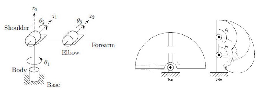
Fig. 3.1 Geometry of a 3-DOF anthropomorphic robot
[Source: Narong Aphiratsakun. AIT]
The serial manipulator shown in figure 3.1 has n=3 joints: each a revolute with 1-DOF. Each joint connects with two links, making the total number of links, n+1 = 4, including the fixed base link.
Therefore, the total number of DOF for any serial manipulator with three 1-DOF joints is:
Note: The DOF of a serial manipulator with only revolute and/or prismatic joints is always equal to the number of its joints, except when both ends of the manipulator are fixed (closed chain linkage).
The workspace of a robotic manipulator is defined as the set of points that can be reached by its end-effector [2]. In other words, it is simply the 3D space in which the robot mechanism works.
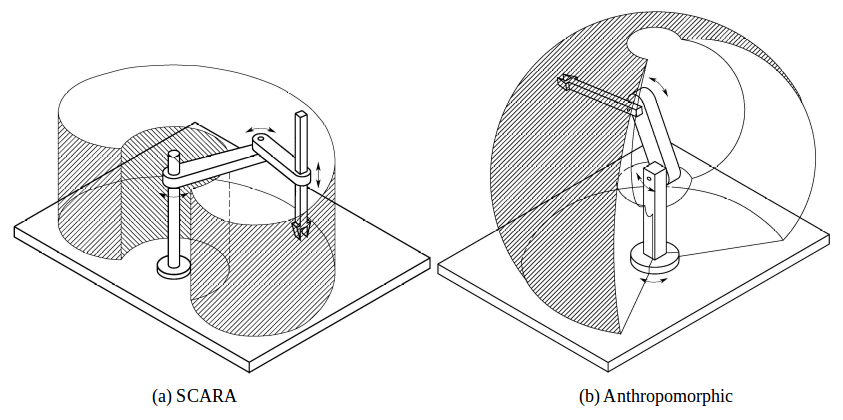
Fig. 3.2 Robot Reach “Bubble”
[Source: Federica.EU]
Figure 3.2 shows two types of serial manipulators, SCARA and Anthropomorphic with their associated workspaces. Figure 3.1 also shows the workspace of the 3-DOF manipulator from a top and side perspective.
It is important to note that no kinematic solution exists for the manipulator's configuration or joint space for any desired end-effector position outside of the workspace.
Rotation matrices are a means of expressing a vector in one coordinate frame in terms of some other coordinate frame.
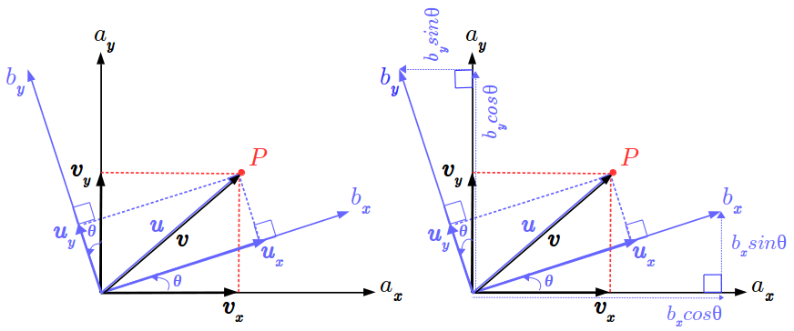
Fig. 3.3 A 2D geometric rotation between coordinate frames A and B
In figure 3.3, Point P is expressed with vector u relative to coordinate frame B. The objective is to express point P with vector v relative to coordinate frame A. The basis vectors of v, vx and vy can be expressed in terms of the basis vectors of u, ux and uy as follows:
where unit vectors of frame A, ax and ay are expressed in terms of unit vectors of frame B, bx and by as follows:
Substituting (2) in (1) and solving for the dot products yields the following equation:
where the first term on the right-hand side is the 2D Rotation Matrix, denoted in this case as abR. Any point on coordinate frame B multiplied by abR will project it onto frame A. In other words, to express a vector u on some frame B as a vector v on a different frame A, u is multiplied by the rotation matrix with angle theta by which frame A is rotated from fram B. Also worth noting is that the rotation from A to B is equal to the transpose of the rotation of B to A.
Euler angles are a system to describe a sequence or a composition of rotations. According to Euler's Rotation Theorem, the orientation of any rigid body w.r.t. some fixed reference frame can always be described by three elementary rotations.
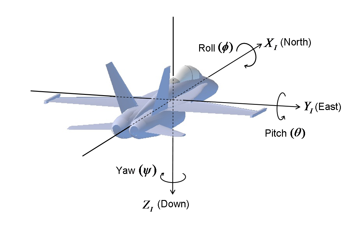
Fig. 3.4 Defining Euler angles from a sequence of rotations
[Source: CHRobotics]
Conventionally, the movements about the three axes of rotations and their associated angles are described by the 3D rotation matrices in figure 3.3.

Fig. 3.5 3D counter-clockwise rotation matrices describing yaw, pitch and roll
Euler angles are characterized by the following properties:
- Tait-Bryan vs. Classic
- Rotation Order
- Intrinsic (body fixed) vs. Extrinsic (fixed axes) rotations
Intrinsic or body-fixed rotations are performed about the coordinate system as rotated by the previous rotation. The rotation sequence changes the axis orientation after each elemental rotation while the body remains fixed.
In an intrinsic sequence of rotations, such as, a Z-Y-X convention of a yaw, followed by a pitch, followed by a roll, subsequent elemental rotations are post-multiplied.
Extrinsic or fixed-axis rotations are performed about the fixed world reference frame. The original coordinate frame remains motionless while the body changes orientation.
In an extrinsic sequence of rotations, such as, a Z-Y-X convention of a yaw, followed by a pitch, followed by a roll, subsequent elemental rotations are pre-multiplied.
Note: An extrinsic rotation sequence of A, B, C = an intrinsic rotation sequence of C, B, A.
Euler angles, normally in the Tait–Bryan, Z-X-Y convention, are also used in robotics for describing the degrees of freedom of a spherical wrist of a robotic manipulator.
Of particular importance is a phenomenon associated with Euler angles known as a Gimbal Lock which occurs when there is a loss of one degree of freedom as a result of the axes of two of the three gimbals driven into a parrallel configuration.
Quaternions are an algebraic structure that extends the familiar concept of complex numbers.A quaternion is a 4-tuple written formally as q0 + q1i + q2j + q3k , where qi are real numbers and the symbols i, j, k sustain an orthogonal system.
From euler angles to a quaternion The formula seems to have been derived this way:
First, roll around the world x axis. The quaternion for this is:
Second, pitch around the world y axis. The quaternion is:
Third, yaw around the world z axis. The quaternion is:
A rotation that is done in steps like this is modeled by multiplying the quaternions.
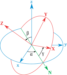
Fig. 3.6 Euler angles for Body 3-1-3 Sequence – The xyz (original fixed Lab) system is shown in blue, the XYZ (rotated final Body) system is shown in red. The line of nodes, labelled N and shown in green, is the intermediate Body X-axis around which the second rotation occurs. A
[Source: Wikipedia]
While quaternions are much less intuitive than angles, rotations defined by quaternions can be computed more efficiently and with more stability, and therefore are widely used.
In the case where a reference frame is both simultaneously rotated and translated (transformed) with respect to some other reference frame, a homogeneous transform matrix describes the transformation.
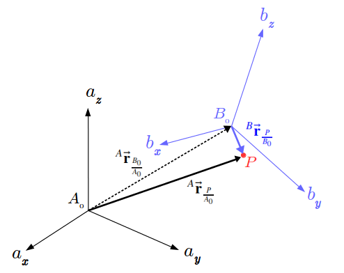
Fig. 3.7 Rotation and Translation of frame B relative to frame A
[Source: Salman Hashmi. BSD License]
In figure 3.7, point P is expressed w.r.t. frame B and the objective is to express it w.r.t. frame A. To do so would require projecting or superimposing frame B onto frame A i.e. first rotating frame B to orient it with frame A and then translating it such that the centers B0 and A0 of both frames are aligned.
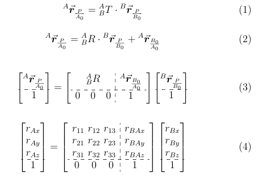
The relationship between the three vectors in figure 3.7 is shown in equation (1). The desired vector to point P from A0 is the sum of the vector to point P from B0, rotated to frame A, and the translation vector to B0 w.r.t A0. Equations (2) and (3) are the matrix-forms of equation (1) so that it can be rendered in software with linear algebra libraries.

Fig. 3.8 Anatomy of the homogeneous transform relationship
Figure 3.8 describes the components of equation (2). The desired vector to point P (w.r.t. to A0) is obtained by multiplying the given vector to point P (w.r.t. B0) by the homogeneous transform matrix, composed of the block Rotation matrix projecting B onto A and the block translation vector to B w.r.t A0.
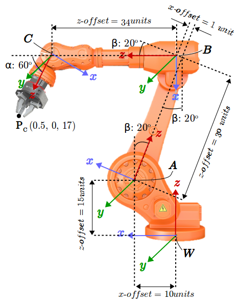
Fig. 3.9 Transformation between adjacent revolute joint frames
As shown in figure 3.9, the position of the end-effector is known w.r.t. its coordinate reference frame C. The objective is to express it w.r.t. the fixed world coordinate reference frame W. This is because the positions of all objects of interest in the manipulator's environment are expressed w.r.t. the world reference frame. In other worlds, both, the end-effector, and the objects it interacts with need to be defined on the same coordinate reference frame.
Point P relative to frame W can be found by successively applying equation (4) between adjacent joints:
The above process can be summarized in terms of equation (1) with WCT being the desired composite homogeneous transform that projects frame C onto frame W.
Before the homogeneous transforms between adjacent links can be computed, the coordinate frames of the joint links on which the transforms are applied must be defined. The Denavit–Hartenberg (DH) parameters are four parameters describing the rotations and translations between adjacent links. The definition of these parameters constitutes a convention for assigning coordinate reference frames to the links of a robotic manipulator. Figure 3.7 shows the so-called modified convention of DH parameters as defined by [Craig, JJ. (2005)].
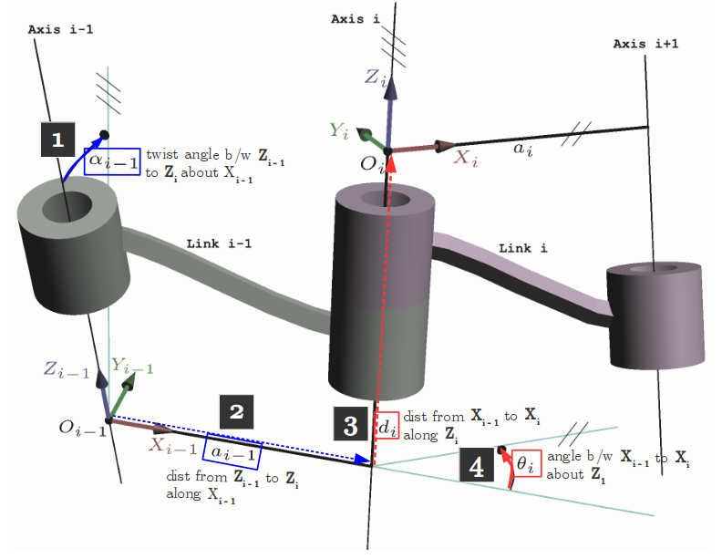
Fig. 3.7 The four parameters of the Modified DH convention
[Source: Modified from Wikipedia Commons]
The parameters are defined as follows:
- αi-1: twist angle between the z-axes of links i-1 and i (measured about xi-1 in a right-hand sense)
- ɑi-1: link distance between the z-axes of links i-1 and i (measured xi-1)
- di: link offset signed distance between the x-axes of links i-1 and i (measured along zi)
- θi: joint angle between the x-axes of links i-1 and i (measured about zi in a right-hand sense)
Note:
- The origin of a frame i is defined by the intersection of xi and zi
- The x-axes define the common normals between zi-1 and zi
Recall that to compute the position of the end-effector w.r.t. the base or world reference frame, transforms between adjacent links are composed as follows:
where the base frame is denoted by 0 and the end-effector's frame denoted by N. Thus, 0NT defines the homogeneous transformation that projects frame N onto frame 0. More specifically, a single transform between links i-1 and i is given by
and is made up up of two rotations R of magnitudes α and θ, and two displacements D of magnitudes ɑ and d.
The parameter assignment process for open kinematic chains with n degrees of freedom (i.e., joints) is summarized as:
- Label all joints from {1, 2, … , n}.
- Label all links from {0, 1, …, n} starting with the fixed base link as 0.
- Draw lines through all joints, defining the joint axes.
- Assign the Z-axis of each frame to point along its joint axis.
- Identify the common normal between each frame Zi-1 and Zi
- The endpoints of intermediate links (i.e., not the base link or the end effector) are associated with two joint axes, {i} and {i+1}. For i from 1 to n-1, assign the Xi to be ...
- For skew axes, along the normal between Zi and Zi+1 and pointing from {i} to {i+1}.
- For intersecting axes, normal to the plane containing Zi and Zi+1.
- For parallel or coincident axes, the assignment is arbitrary; look for ways to make other DH parameters equal to zero.
- For the base link, always choose frame {0} to be coincident with frame {1} when the first joint variable (θ1 or d1) is equal to zero. This will guarantee that α0 = a0 = 0, and, if joint 1 is a revolute, d1 = 0. If joint 1 is prismatic, then θ1 = 0.
- For the end effector frame, if joint n is revolute, choose Xn to be in the direction of Xn−1 when θn = 0 and the origin of frame {n} such that dn = 0.
Special cases involving the Zi-1 and Zi axes:
- collinear lines: alpha = 0 and a = 0
- parallel lines: alpha = 0 and a ≠ 0
- intersecting lines: alpha ≠ 0 and a = 0
- If the common normal intersects Zi at the origin of frame i, then di is zero.
Once the frame assignments are made, the DH parameters are typically presented in tabular form (below). Each row in the table corresponds to the homogeneous transform from frame {i} to frame {i+1}.
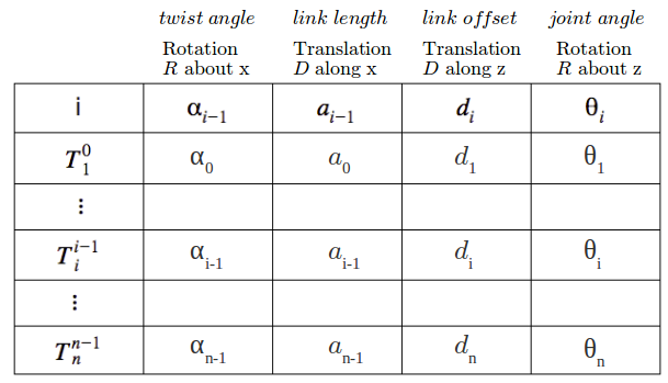
Table 3.1 The four parameters of the Modified DH convention
Forward Kinematics is the process of computing a manipulator's end-effector position in Cartesian coordinates from its given joint angles. This can be achieved by a composition of homogeneous transformations that map the base frame onto the end-effector's frame, taking as input the joint angles. The end-effector's coordinates can then be extracted from the resulting composite transform matrix.
The relationship between Forward and Inverse Kinematics is depicted in figure 3.9,
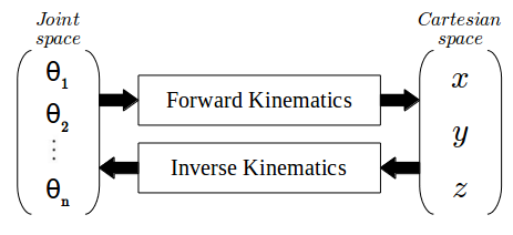
Fig. 3.8 Relationship between Forward and Inverse Kinematics
Inverse Kinematics is the reverse process where the EE position is known and a set of joint angles that would result in that position need to be determined. This is a more complicated process than FK as multiple solutions can exist for the same EE position. However, no joint angle solutions exist for any EE position outside the manipulator's workspace. There are two main approaches to solve the IK problem: numerical and analytical. The later approach is used in this project.
The robot we use is a two-wheeled (motorized) robot. Each of the wheels can rotate back and forth separately. Let’s define the dynamical model:
- (x,y) - the position of the robot
- θ - the orientation of the robot
- v- measured linear velocity
- ω - measured angular velocity let's write the derivatives of the position and the orientation,
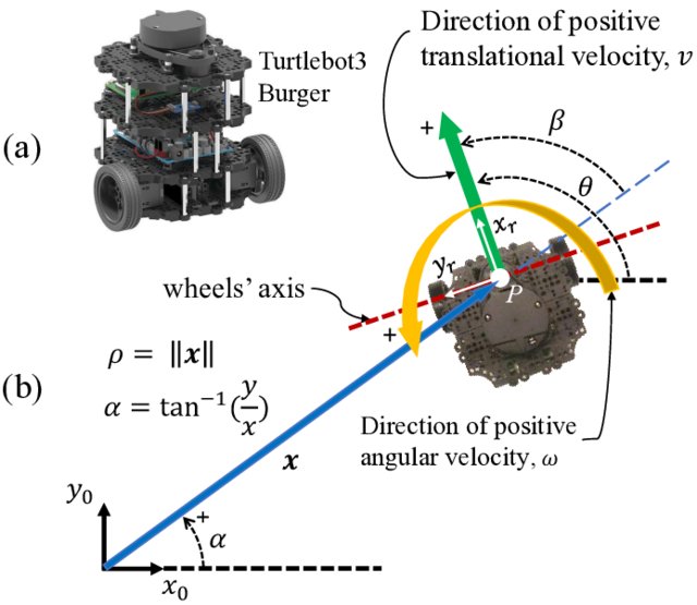
Fig. 3.9 (a) 3-D view of the Turtlebot3 Burger robot, and (b) definitions of the state variables ρ, α, and θ in an overhead view of the robot.
[Source:Amir Salimi Lafmejani. Researchgate]
In the robot we control at, their only the velocity of the two wheels Let’s define it in our model:

Fig. 3.9 Geometric description of the robot movement
As we can see d is the distance between the two TB3 centers. Form geometric calculations we get:
and,
We can derivate the following expressions and use the relationship between v and ω:
- r - the radios of the wheel
- L - the distance between the wheels
- vr - right wheel velocity
- vl - left wheel velocity
so,
If we compare coefficients
we can express the measured linear
and angular velocities depending on
:
so,
hence,
The Robot Operating System (ROS) is a set of software libraries and tools used to build robotic systems. ROS is known for a distributed and modular design. Given a model of the environment, task planning is concerned with the assembly of actions into a structure that is predicted to achieve goals.
- manager of the ROS Nodes
- allows _Nodes to locate one another and communicate
- also hosts the _Parameter_Server so running _Nodes can lookup parameter and configuration values e.g. wheel radius
- More Explanation:
- maintains a registry of all the active nodes on a system. It then allows these nodes to discover other nodes to establish lines of communications between nodes i.e. the nodes themselves don't have to communicate to other nodes through the ROS master; they can do it directly once the ROS master has allowed them to discover other relavant nodes for communication.
- Through _Topics or _Services
- Pub-Sub comm pattern vs, Req-Res comm pattern
- Pub-Sub comm pattern:
- _Nodes can also share data (i.e. publish and subsrcribe _Messages) amongst themselves via nameds buses called _Topics. (Recall that the only stuff that nodes and ROS master share are Parameter values)
- Nodes publish and subscribe _Messages over _Topics
- Req-Res comm architecture:
- Like _Topics, _Services allow the passing of message betwee nodes
- Before we can launch and use a ROS package like turtlesim, we must first ensure that all of the ROS environment variables have been correctly set.
- Your ROS distro e.g. Kinetic provides a bash script called setup.bash to ensure this.
- This script can be run with the bash command: source
- Among other things, the ROS environment variables tell our bash shell where ROS commands and packages can be found.
- rosout node is responsible for aggregating, filtering and recording log messages to a text file.
- a powerful build and package management system provided by ROS.
- a catkin workspace is a direcoty where catkin packages are built, modified and installed
- all ROS software components are organized into and distributed as catkin packages
- catkin packages contain resources like source code for nodes, useful scripts, config file etc.
- Launch ROS Master and multiple nodes with one simple command
- Set default parameters on the parameter server
- Automatically re-spawn processes that have died
- The ROSPlan framework provides a collection of tools for AI Planning in a ROS system. ROSPlan has a variety of nodes which encapsulate planning, problem generation, and plan execution. It possesses a simple interface, and links to common ROS libraries.
- ROSPlan has a modular design, intended to be modified. It serves as a framework to test new modules with minimal effort. Alternate approaches to state estimation, plan representation, dispatch and execution can be tested without having to write an entire framework.
Run of the simulation on double time
simX2.mp4
Udacity RoboND Pick & Place. (2017). Salman Hashmi. https://github.com/Salman-H/pick-place-robot
Narong Aphiratsakun. (2015). MT411 Robotic Engineering, Asian Institute of Technology (AIT). http://slideplayer.com/slide/10377412/
Siciliano et al. (2010). Robotics: Modelling, Planning and Control, (Springer)
Elashry, Khaled & Glynn, Ruairi. (2014). An Approach to Automated Construction Using Adaptive Programing. 51-66. 10.1007/978-3-319-04663-1_4, (Springer)
Yi Cao, Ke Lu, Xiujuan Li and Yi Zang (2011). Accurate Numerical Methods for Computing 2D and 3D Robot Workspace [Journal] // International Journal of Advanced Robotic Systems : INTECH, August 2011. – 6 : Vol. VIII – pp. 1-13.
Understanding Euler Angles. CHRobotics. http://www.chrobotics.com/library/understanding-euler-angles
Craig, JJ. (2005). Introduction to Robotics: Mechanics and Control, 3rd Ed (Pearson Education)
