TwoWheelCar-STM32-F401RE
This repository contains the proposed solution for the assigned project Two Wheel Car for STM32 Nucleo F401RE board" in the course of Embedded Systems, master degree in Computer Engineering @ Università degli Studi di Salerno.
Hardware Achitecture
Pinout
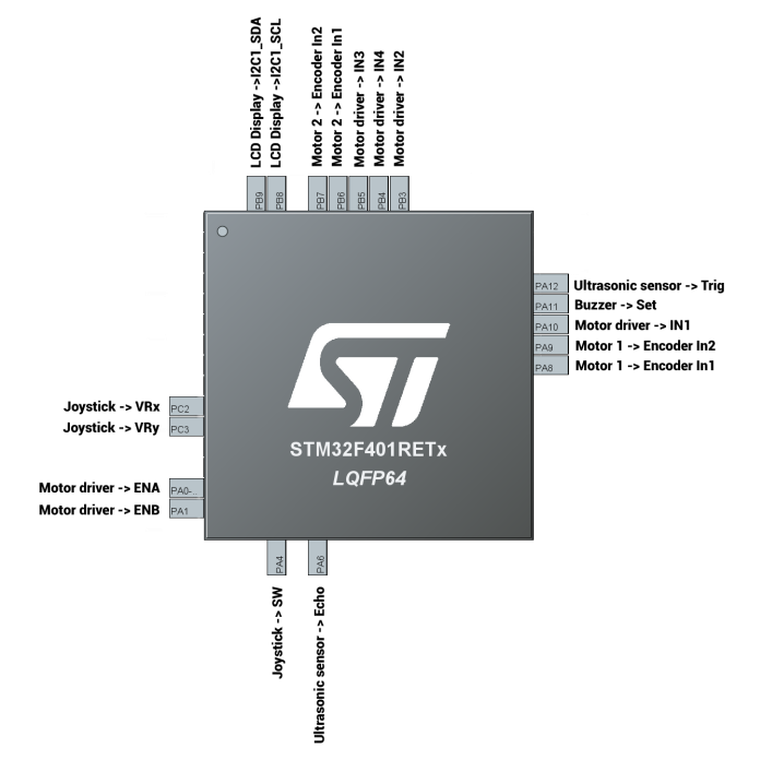
The following schema provides a general view about connections between the board and its pins with all the module used:
Clock tree
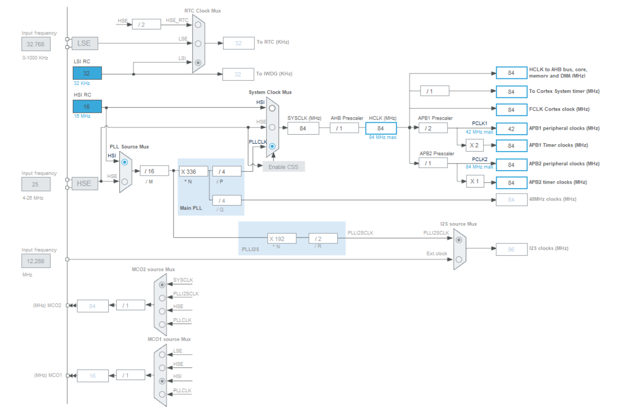
The following image describes the clock tree of the board. In order to achieve a good performance with the ultrasonic module, to produce the trigger signal required and calculate with a good accuracy the time of flight of the sound waves and estimate in a correct way the distance from an obstacle, it has been decided to set the HCLK and the APB1/APB2 timer clocks at 84 MHz.
Components overview
An overview of every single component of the board used is provided:
GPIO
- PA4: is used to acquire the external event “stick pressed”
- GPIO mode: External Interrupt Mode with Falling edge trigger detection
- GPIO Pull-ip/Pull-down: Pull-up
- EXTI line4 interrupt: Enabled
- EXTI line4 interrupt: Enabled
- GPIO mode: Output push pull
- PA11: is used to control the S input of the active buzzer
- GPIO mode: Output push pull
- PA12: is used to control the Trig input of the Ultrasonic Sensor module, when the output is High for 10 μs the sonar is started
- GPIO mode: Output push pull
- GPIO mode: Output push pull
- GPIO mode: Output push pull
- PB4: is used to control the IN4 input of the motor driver
- GPIO mode: Output push pull
- PB5: is used to control the IN3 input of the motor driver
- GPIO mode: Output push pull
Timers
- TIM1 / TIM4: are used in encoder mode to read the current speed of the motors
- Pin used:
- PA8: TIM1_CH1
- PA9: TIM1_CH2
- PB6: TIM4_CH1
- PB7: TIM4_CH2
- Prescaler: 84-1
- Counter mode: Up
- Counter Period: 1000-1
- Pin used:
- TIM2: is used to generate two PWM that controls the DC Motors speed
- PIN used:
- PA0: TIM2_CH1
- PA1: TIM2_CH2
- Clock source: internal
- Channel1: PWM Generation CH1
- Channel2: PWM Generation CH2
- Prescaler: 8400-1
- Counter mode: Up
- Counter Period: 1000-1
- PIN used:
- TIM3: is used to capture the both the edges of the sound wave and calculate the time of flight.
- PIN used:
- PA6: TIM3_CH1
- Clock source: internal
- Channel1: Input Capture direct mode
- Prescaler: 84-1
- Counter mode: Up
- Counter Period: 1000000-1
- Polarity Selection: Both Edges
- TIM3 global interrupt: Enabled
- PIN used:
- TIM9: is used to prevent the debouncing phenomenon of the stick button.
- Clock source: internal
- Prescaler: 8400-1
- Counter mode: Up
- Counter Period: 500-1
- TIM9 global interrupt: Enabled
- TIM10: is used to produce a periodic signal, based on the distance of the obstacle in front of the
car, that turns on the active buzzer.
- Clock source: internal
- Prescaler: 84000-1
- Counter mode: Up
- Counter Period: 1000-1
- TIM10 global interrupt: Enabled
- TIM11: is used to generate a trigger signal that lasts 10 μs that starts the sound waves emission.
- Clock source: internal
- Prescaler: 84-1
- Counter mode: Up
- Counter Period: 0
Analog
- ADC1: is used to acquire the position of the joystick that controls the vehicle.
- PIN used:
- PC2: ADC1_IN12
- PC3: ADC1_IN13
- Channel 12: used to acquire x-axis position
- Channel 13: used to acquire y-axis position
- DMA Settings
- DMA Request: ADC1
- Stream: DMA2 Stream 0
- Direction: Peripheral To Memory
- Priority: Low
- Mode: Normal
- Data Width: Word
- PIN used:
Connectivity
- ADC1: is used to acquire the position of the joystick that controls the vehicle.
- PIN used:
- PC2: ADC1_IN12
- PC3: ADC1_IN13
- Channel 12: used to acquire x-axis position
- Channel 13: used to acquire y-axis position
- DMA Settings
- DMA Request: ADC1
- Stream: DMA2 Stream 0
- Direction: Peripheral To Memory
- Priority: Low
- Mode: Normal
- Data Width: Word
- PIN used:
Software Architecture and Interfaces
Besides the normal files provided automatically from STM32CubeIDE in every project, in Core/Inc and Core/Src can be found the header and source files for the modules used in this project.
Motor
This library manages a single DC Motor and provides all the functions needed in order to start and stop the motor and set speed and direction. In the “Motor.h” file is defined the motor_class struct:
- htim: pointer to the timer that generates the PWM in order to set speed
- timer_channel: indicates which channel of the timer is used
- GPIOx_IN1: indicates which set of GPIO pin is used to control the first input of the motor driver
- GPIOx_IN2: indicates which set of GPIO pin is used to control the second input of the motor driver. Both are used to set the direction of the motor
- GPIO_Pin_IN1: indicated the pin number used to control the first input of the motor driver
- GPIO_Pin_IN2: indicated the pin number used to control the second input of the motor driver
- stopped: 1 if the motor is stopped, 0 otherwise
- htim_encoder: pointer to the timer in encoder mode that reads the speed
- htim_encoder_frequency: frequency of the timer used in encoder mode
- cnt1 / cnt2: variables used to calculate the current speed
- diff: variables that contains cnt2 – cnt1
- error: difference between the current speed and the desired one
- prev_error: previous error computed
- historic_error: sum of the errors
- pwm: variable that contains the pwm value computed.It is also defined an enum called DIRECTION, used to set the direction of the motor
The following table describes the interface of this module:
- motor__init__: initialize the motor_class struct
- motor_start: it starts the timer with the HAL_TIM_PWM_Start function, provided by the Hardware Abstraction Layer, and sets stopped = 0
- motor_set_speed_and_direction: if the motor isn’t stopped, set the duty cycle appropriately in order to achieve the desired speed and set the direction: if FORWARD,GPIO_Pin_IN1 is setted and GPIO_Pin_IN2 is resetted, using the HAL_GPIO_WritePin function, viceversa if BACKWARD
- motor_stop_and_go: stops the the PWM timer and resets the two IN1 and IN2 pins if stopped == 1, otherwise it starts the motor calling motor_start
- motor_is_stopped: returns the value of the stopped variable
- _motor_compute_current_speed: compute the current speed of the motor, based on the data of the encoder
- _PID: using a PID controller, computes the pwm value in order to get the desired speed, based on the current speed and error
- motor_get_current_speed: returns the current speed
- motor_get_pwm: returns the current pwm value
Sonar
This library manages the ultrasonic module and provides all the function required to start the sonar, acquire the sound waves and compute the distance. In the “Sonar.h” file is defined the sonar_class struct:
- reading_edge: indicates what edge of the wave the sonar is reading: 0 if rising edge, 1 if falling
- T1: stores the starting time
- T2: stores the ending time. The duration of the sound wave is T2-T1.
- TIMER_OVERFLOW: stores the number of timer overflows occured. T2 = T2 + TIMER_OVERFLOW * ARR of the timer
- distance: stores the distance computed from the obstacle
- htim: pointer to the timer used to capture the sound wave and calculate the time of flight
- htim_delay: used to produce a signal that lasts 10 μs in order to start the sonar
- GPIOx: indicates which set of GPIO pin is used for the trigger input of the sensor
- GPIO_Pin: indicated the pin number used to for the trigger input of the sensor
- timer_channel: indicates what is the channel of the timer used to capture the sound wave
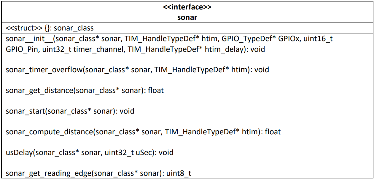
The following table describes the interface of this module:
- sonar__init__: initialize the sonar_class struct
- sonar_timer_overflow: when the timer overflow event occurs, increment the TIMER_OVERFLOW variable
- sonar_get_distance: returns the value of the last distance computed
- sonar_start: it triggers the 10 μssignal in order to start the ultrasonic module. It also starts the timer that acquires the sound wave and computes the time of flight by the HAL_TIM_IC_Start_IT function
- sonar_compute_distance: is called twice for acquisition, one for each edge, when a capture event is detected by the CaptureCallback function.
- If it’s the rising edge, then stores the time value in T1, using the HAL_TIM_ReadCapturedValuefunction and return -1
- If it’s the falling edge, then stores the time value in T2, calculate the correct time due to eventually overflow occurred and then computes the distance as (T2 – T1) * (0.0343/2) and stores in the distance variable. It also stops the timer from capture task and returns the distance
- usDelay: utility function, used to produce the 10 μs longer desired signal
- sonar_get_reading_edge: returns the value of the reading_edge variable
Buzzer
This library manages the active buzzer module and provides all the function required to set and produce the desired alarm, in relation with the distance from the obstacle. In the “Buzzer.h” file is defined the buzzer_class struct:
- htim: pointer to the timer used to produce the alarm at the desired frequency
- GPIOx: indicates which set of GPIO pin is used for the Set input of the buzzer
- GPIO_Pin: indicated the pin number used to for the Set input of the buzzer
- count: utility variable, used to produce the alarm sound at the desired frequency
- alarm: indicates which kind of alarm frequency is desired
It is also defined an enum called ALARM_TYPE, used to set which kind of alarm frequency is desired.
The following table describes the interface of this module:
- buzzer__init__: initialize the buzzer_class struct
- buzzer_set_alarm: sets the desired kind of alarm
- buzzer_beep: this function is called every time the TIM10 PeriodElapsed event occurs by the PeriodElapsedCallback (every 0.1 second), in order to produce the desired kind of alarm:
- If alarm == NO_ALARM, then the buzzer is muted
- If alarm == DANGER_ALARM, then the buzzer produce an continous alarm
- Otherwise, the count variable is setted in this way:
- buzzer->count = (buzzer->count + 1)%(10/buzzer->alarm)
- If count == 0, the output pin is setted and the buzzer produce noise, otherwise is resetted. In this way:
- If alarm == ALARM_1, then a 0.1 s beep longer is produced every 1 s
- If alarm == ALARM_2, then a 0.1 s beep longer is produced every 0.5 s
- If alarm == ALARM_4, then a 0.1 s beep longer is produced every 0.25 s
- ALARM_3 is unused
I2C-lcd
This library manages the lcd display and provides all the function required to visualize a text on it, in particular in this project is used to visualize the distance from the obstacle. The slave address is: 0x4E.
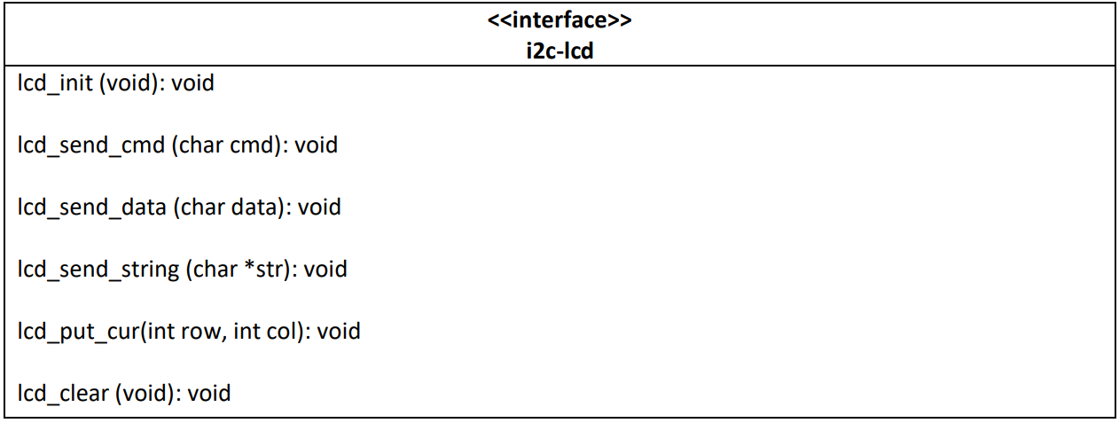
The following table describes the interface of this module:
- lcd_init: initialize and turns on the display
- lcd_send_cmd: utility function, used by the others to send commands to the display
- lcd_send_data (char data): used to send a character to the display at the current position of the cursor
- lcd_send_string: used to send an entire string to the display
- lcd_put_cur: used to select the position of the cursor
- lcd_clear: used to clear the display from the current strings
Main
The main.c file contains the logic of the program and connect all the modules described above. For the purpose of the project, the following function were added:
- GetAlarmType: returns the desired alarm type based on the distance from the obstacle
- CaptureCallback: this function is called by HAL_TIM_IC_CaptureCallback (stm32f4xx_it.c). Calls sonar_compute_distance and sets the buzzer’s alarm type in according to the distance
- PeriodElapsedCallback: this function is called by HAL_TIM_PeriodElapsedCallback (stm32f4xx_it.c). If the instance of the timer that fired the interrupt is TIM3, it calls sonar_timer_overflow. In case the instance is TIM10, calls buzzer_beep
- HAL_ADC_ConvCpltCallback: is the callback function of the ADC, initialized in main in DMA mode using the HAL_ADC_Start_DMA function. It reads the x and y values of the joystick, converts them in the range [-100, 100], and sets the correct speed and direction of the DC Motors by the motor_set_speed_and_direction function. It also has a calibration procedure the first time is called
- The DC motors used have a max speed of 100 rpm, so mapping the values of the joystick position in range [-100,100] permits to set precisely the desired velocity
- Emergency_Stop_And_Go: when the stick is pressed, an interrupt is fired and the HAL_GPIO_EXTI_Callback function (stm32f4xx_it.c) is called. In order to avoid debouncing, TIM9 is started with a period of 50ms. Then, when the period is elapsed, an interrupt is fired and HAL_TIM_PeriodElapsedCallback is called. The callback finally invokes Emergency_Stop_And_Go, that calls motor_stop_and_go


