This project realizes sending UART serial protocol data via power line, the sender being an Arduino board, the receiver is a Raspberry Pi with a Python program which publishes to MQTT.
The challenge has been to send data (e.g., temperature sensor readings) from an outside garage to a server (RasPi) inside the main house.
The gerage is located some distance away from the house and multiple concrete walls are blocking the line of sight, making radio communication impossible.
But, there is one single phased power line between the house and the garage. Just the power line, no empty conduit.
The solution approach is to use the power line as carrier. A power line modem is used to send sensor readings periodically over the power line.
The involved components:
- Arduino Pro mini as sender
garagenode_sender/garagenode_sender.ino
- Raspberry Pi 2a as receiver
garagenode_receiver/garagenode_receiver_mqtt.py
- 2 power line modems, KQ-330F (KQ-330), UART
Schematics:
SENSORS <---> Arduino <---> Modem <-- Power line --> Modem <---> Raspberry Pi
- Arduino Board, e.g. Arduino Pro Mini
- Arduino Libraries:
- SoftwareSerial (included in Arduino SDK)
- DHT, https://github.com/adafruit/DHT-sensor-library/releases/tag/1.4.3
- Deep sleep, https://github.com/n0m1/Sleep_n0m1/releases/tag/v1.1.1
- Python 3.5+
- Install needed libraries with
pip3 install -r requirements.txt
- Install needed libraries with
- MQTT Server
- Install neccessary Arduino libraries, see above and
garagenode_sender/garagenode_sender.ino. - Open
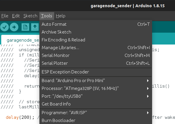
garagenode_sender/garagenode_sender.inoin Arduino IDE - Select
- Compile / verify
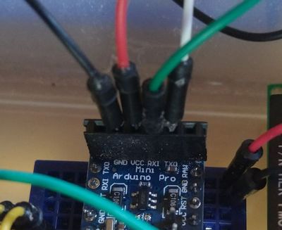
- Connect USB-Serial (TTY) to RXD, TXD, GND and VCC.
- Upload: click on upload and in the very next second reset Arduino by pressing button (or shortly connecting RST+GND)
- Done flashing.
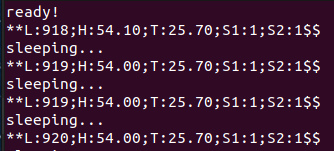
- Check if it's working:
- Plug into power-line.
- Preparation:
- Setup MQTT server
- Setup wiring on RasPi, refer to wiring library documentation.
-
Hardware Setup
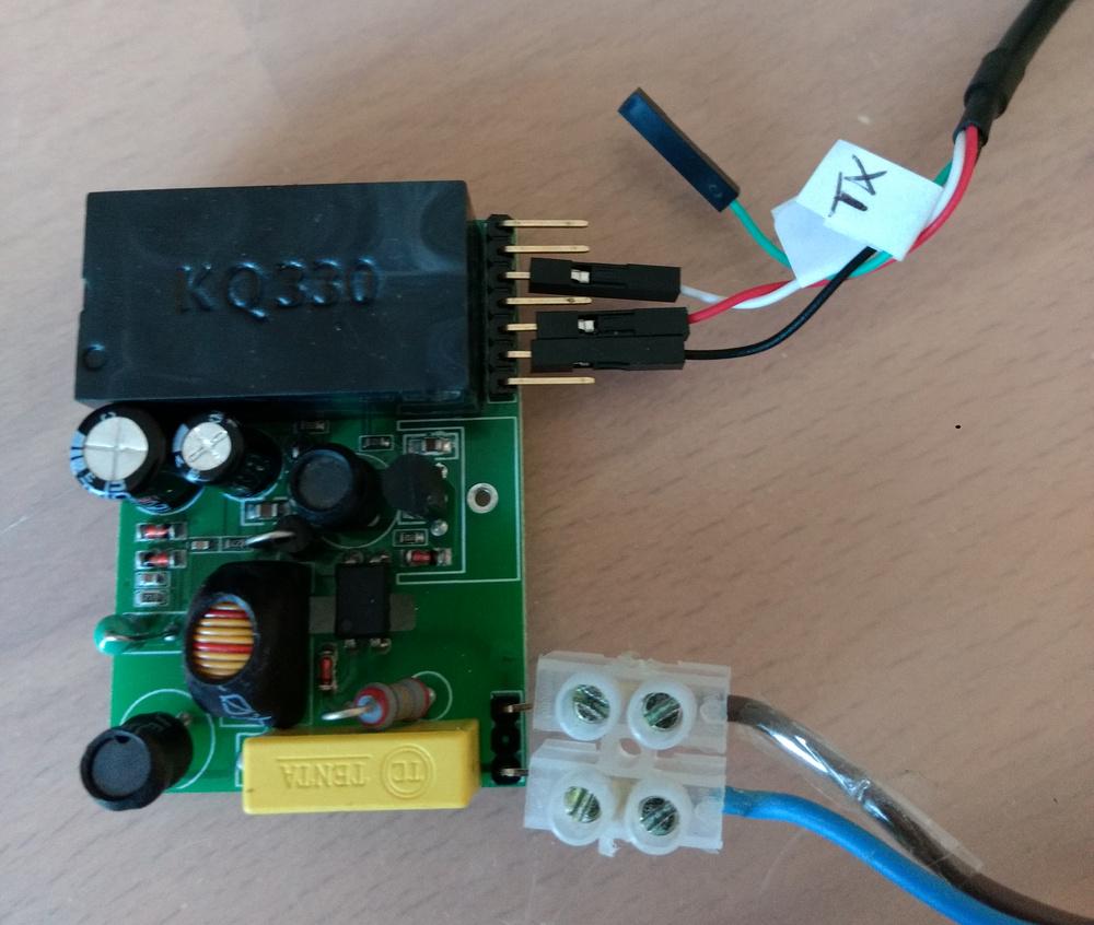
RasPi KQ330 Powerline Modem +5 VCC VCC GND GND RXD = Pin 10 = WiringPi 16 = GPIO 15 TX -
Install Python libraries with
pip3 install -r requirements.txt -
python garagenode_receiver/garagenode_receiver_mqtt.py /dev/ttyAMA0 9600This assumes a MQTT server on localhost. If not, then look at the CLI parameters (--help).
A systemd-service-script is located in garagenode_receiver/systemd/garagenode.service.
For install, copy to /etc/systemd/system and enable with systemctl enable garagenode.service.
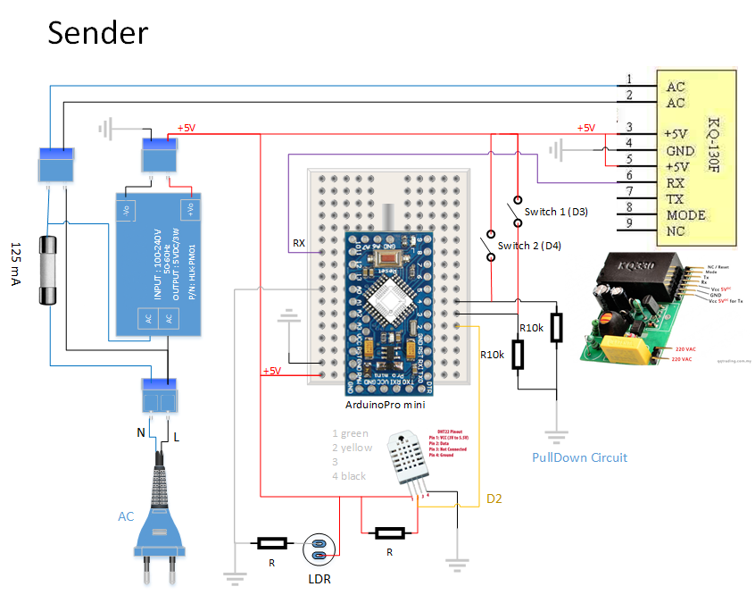
The sender has:
- Fuse 125 mA
- KQ-330F, sender pin is RX (!), connected to Arduino D11
- DHT22, Arduino D2
- LDR, Arduino A0
- switch 1, Arduino D3, pulldown circuit
- switch 2, Arduino D4, pulldown circuit
| State | V | mA | digitalRead |
|---|---|---|---|
| open | 0,0 V | 0,43 mA | 1 |
| close | 4,4 V | 0,0 mA | 0 |
open: e.g., door open, water-level high
close: e.g., door closed, water-level low
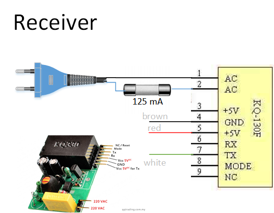
The receiver has:
- Fuse 125 mA
- KQ-330F, receiver pin is TX (!), connected to e.g. RasPi
- KQ-130F
- Mamba - Narrow Band Powerline Communication Shield for Arduino
- X10 Protokoll (129 kHz)
- https://en.wikipedia.org/wiki/X10_(industry_standard)
X10 is a protocol for communication among electronic devices used for home automation (domotics). It primarily uses power line wiring for signaling and control, where the signals involve brief radio frequency bursts representing digital information.
- https://www.remote.org/frederik/projects/x10/index.html.de
- X-10 and 230V
- X10 XM10 Zwei-Wege-Powerline-Interface, 50 €, https://www.intellihome.be/de/x10-xm10-zwei-wege-powerline-interface.html
- Arduino X10 library, https://www.arduino.cc/en/Tutorial/x10
- CM15 Pro - Enhanced Computer Interface Module ($139.00), http://www.whomedigital.com.au/prod3.htm
- https://en.wikipedia.org/wiki/X10_(industry_standard)
- HomePlug Green PHY
- https://de.wikipedia.org/wiki/Tr%C3%A4gerfrequenzanlage
Als Trägerfrequenzanlage (TFA) bezeichnet man eine Vorrichtung zur Sprach- oder Datenübertragung über vorhandene Kommunikations- oder Stromnetze.
- Hardware
- https://stackoverflow.com/questions/815758/simple-serial-point-to-point-communication-protocol
- HDLC High-Level Data Link Control
- High-Level Data Link Control (HDLC) is a bit-oriented code-transparent synchronous data link layer protocol developed by the International Organization for Standardization (ISO). The standard for HDLC is ISO/IEC 13239:2002.
- https://en.wikipedia.org/wiki/High-Level_Data_Link_Control
- HDLC library for arduino , https://github.com/mengguang/ArduinoHDLC
- Modbus
- Modbus is a serial communications protocol originally published by Modicon (now Schneider Electric) in 1979 for use with its programmable logic controllers (PLCs). Modbus has become a de facto standard communication protocol and is now a commonly available means of connecting industrial electronic devices.
- https://en.wikipedia.org/wiki/Modbus
- https://www.arduino.cc/en/ArduinoModbus/ArduinoModbus
Various approaches exist to reduce the power consumption of an Arduino. Of high impact is often to remove the power LED.
| Mode | with power LED | without power LED |
|---|---|---|
| Idle | 9.5 mA | 6 mA |
| Power Down Sleep | 2.9 mA (0.01 W) | 0.15 mA (0.000495 W) |
| Sending | 9 mA | 1.2 mA |
3.3 V * 0.00015 A = 0,000495 W
3.3 V * 0.0029 A = 0,00957 W
AGPL3, see LICENSE.

