To implement 8 to 3 Encoder and 3to8 Decoder using verilog and validate its outputs
PC, Cyclone II , USB flasher
Quartus prime
Binary code of N digits can be used to store 2N distinct elements of coded information. This is what encoders and decoders are used for. Encoders convert 2N lines of input into a code of N bits and Decoders decode the N bits into 2N lines.
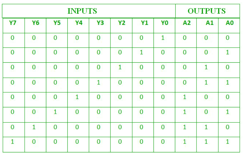
- Encoders – An encoder is a combinational circuit that converts binary information in the form of a 2N input lines into N output lines, which represent N bit code for the input. For simple encoders, it is assumed that only one input line is active at a time.
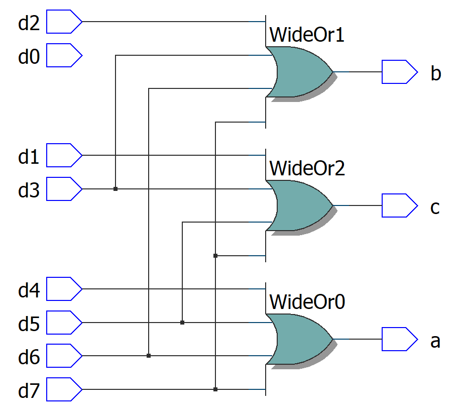
As an example, let’s consider Octal to Binary encoder. As shown in the following figure, an octal-to-binary encoder takes 8 input lines and generates 3 output lines.
Implementation –
X = D4 + D5 + D6 + D7
Y = D2 +D3 + D6 + D7
Z = D1 + D3 + D5 + D7
Hence, the encoder can be realised with OR gates as follows:
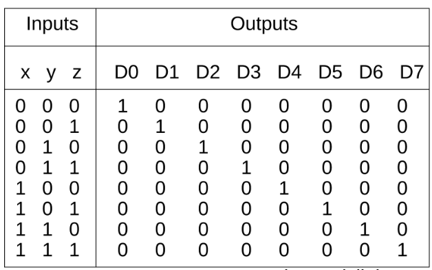
A decoder does the opposite job of an encoder. It is a combinational circuit that converts n lines of input into 2n lines of output.
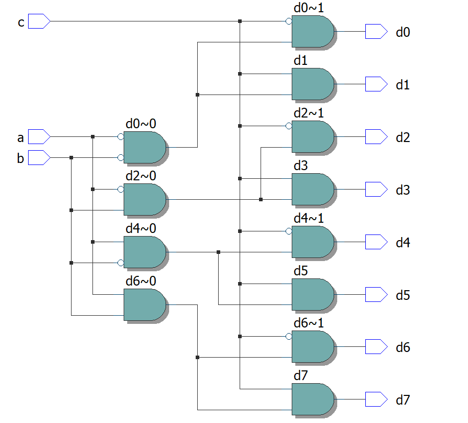
Let’s take an example of 3-to-8 line decoder. Implementation – D0 is high when X = 0, Y = 0 and Z = 0. Hence,
D0 = X’ Y’ Z’
Similarly,
D1 = X’ Y’ Z
D2 = X’ Y Z’
D3 = X’ Y Z
D4 = X Y’ Z’
D5 = X Y’ Z
D6 = X Y Z’
D7 = X Y Z
Module Declaration. module is a keywords defined in Verilog .
Input-Output Delecaration.
8 to 3 Encoder has eight inputs and three outputs. 3 to 8 Decoder has three inputs and eight outputs.
In the verilog program of encoder we use or gates . In the verilog program of decoder we use only and gates.
Ending module. endmodule is a keywords defined in Verilog
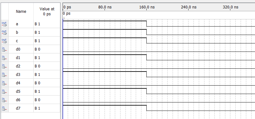
Program for Endocers and Decoders  and verify its truth table in quartus using Verilog programming.
Developed by: Jegatish S
RegisterNumber:  212221230041
module encoder(a,b,c,d0,d1,d2,d3,d4,d5,d6,d7);
input d0,d1,d2,d3,d4,d5,d6,d7;
output a,b,c;
or(a,d4,d5,d6,d7);
or(b,d2,d3,d6,d7);
or(c,d1,d3,d5,d7);
endmodule
module decoder(d0,d1,d2,d3,d4,d5,d6,d7,a,b,c);
input a,b,c;
output d0,d1,d2,d3,d4,d5,d6,d7;
assign d0=(~a & ~b & ~c);
assign d1=(~a & ~b & c);
assign d2=(~a & b & ~c);
assign d3=(~a &b & c);
assign d4=(a & ~b & ~c);
assign d5=(a & ~b & c);
assign d6=(a & b & ~c);
assign d7=(a & b &c);
endmodule
Implementation of 8 to 3 Encoder and 3 to 8 Decoder is done using verilog and its outputs is validated.


