System developed for automatic watering of plants.
Every plant needs different rate of watering and soil humidity, e.g. Cyperus needs a lot of water, the swamp is ideal. Contrary Zamioculcas likes small amount of water in shady places, and dry soil. Simple drop waterer or water dispenser can not do this. One can solve some problems by self watering pots, but they have mostly limited water volume.
Similar projects (other exists): Parrot Flower Power, Edyn, OpenSprinkler.
These projects are either expensive (the project was aimed in the beginning for 14 power pots, every one with different plant), or not suitable to my needs. Probably there exists at least one suitable and cheap enough project in the world, but I couldn't find it in 2013 and it was fun to develop it. And... it is not finished, never will be, so I have something to do till my end of life.
- Raspberry Pi: ~37 euro
- Valves: 14*5.5 = 78 euro
- Pump: 17 euro
- Power source: ~33 euro
- PCBs: ~75 euro
- Sensors etc: ~75 euro
- Total: something about 315 euro
Compare this to the OpenSprinkler (145 euro for DIY version and zone expander), which can not water pot by soil humidity. Anyway I owe a lot of inspiration and learned code to the OpenSprinkler and OpenSprinklerPi.
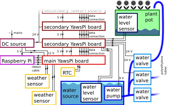
The watering system is built in such way that: there is one water source (e.g. barrel of water, or water tap). A pump is used to pump water from water source. Water is leaded by tubes into several valves. From valves water is leaded to the plant pots. Control software always open only one valve, so only one water pump is required and software can direct water from water source to the desired plant pots. Every plant pot and water source can have one water level sensor.
System can be set to water plants in plant pots in three different ways:
- watering based on water level or soil humidity of the plant pot,
- watering based on the day of the week and hour of the day and on the water level or soil humidity of the pot,
- watering every Nth day and hour and on the water level or soil humidity of the pot.
The system logs watering and weather, so hopefully I will be able to relate temperature/humidity to the water consumption of particular plants. The plan is also to increase or decrease frequency of watering depending on the temperature/humidity/rain.
System consists of:
- Hardware with components:
- controlling computer Raspberry Pi,
- power supply,
- water pump,
- water valves,
- water level sensors (optional),
- weather sensors (optional),
- water tubes.
- YawsPi electronics,
- Software with components:
- Hardware modules,
- hardware configuration,
- hardware abstraction layer,
- main program running in two threads, one is for watering, second one is for web server.
System was built up on Raspberry Pi, but any other with general purpose input/output ports and able to run python can be used.
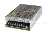
Raspberry Pi requires 5 V, water pump requires 6-9 V, water valves requires 24 V. Switching power supply Mean Well RQ-85D was selected. It has got one 5 V, 6 A output, one 12 V 2 A output, one 24 V 1 A output and one -12 V 0.5 A output. Datasheet.
You can buy one in shops with electronics, like http://www.gme.cz or http://www.farnell.com.
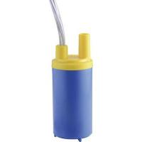
Immersible Barwig BW04 water pump was used. It can pump up to 10 l/min. For continuous usage needs 6 to 9 V power source. It was immersed directly into the barrel - water source. Datasheet.
You can buy it e.g. at http://www.conrad.cz.
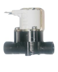
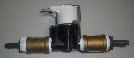
The cheapest water valve I was able to find was VIVA Sanela VE-RPE4115NC. It is monostable DC coil powered by 24 V, normally closed, i.e. without any power it is closed. That was the safety requirement - if the power goes wrong, water is stopped. It is used in water plumbing, so you can buy such valve in several shops, like: http://www.sanela.cz/.
Water level sensors are two types: binary or gradual.
I used these two:
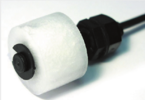
Hamlin sensor (or copies from http://dx.com/), which is based on floating magnet, and changes resistance from less than 1 Ohm to more than 10^9 Ohm. It is attached vertically and is good for pots. Datasheet
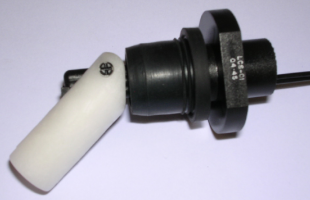
Gentech sensor (or copies from http://dx.com/), which is based on floating magnet similarly as previous sensor. It is attached horizontally and is good for barrel of water source. Datasheet
Both sensors are just connected to digital input of a port expander.
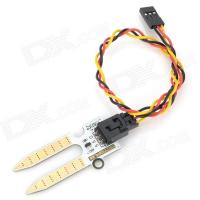
I am still testing gradual sensors, mainly this one for soil humidity: http://www.dx.com/p/freaduino-soil-humidity-sensor-for-arduino-white-147817
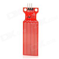
and this one for water level: http://www.dx.com/p/062301-water-sensor-working-with-official-arduino-products-red-228292.
Problem of such sensors is durability. Water or humid soil is corrosive. When switched on, it corodes even more. The first one is good because it is gold plated. It gives output of 0 V to 5 V in dry to humid soil (when powered by 5 V). The second one is much cheaper, it can sustain long time in water, but degrades quickly when powered. It gives output of 0 V to 5 V according water level. Corrosion is the reason why the power to gradual sensor is switched on only during measurement.
Following weather sensors are implemented:
- Air temperature
- Air humidity
- Air pressure
- Ambient illuminance
- Rain status
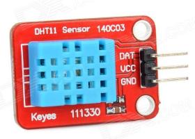
The ambient temperature can be measured either by DHT11 sensor (used for air humidity) or BMP180 sensor (used for air pressure).
The humidity is measured by DHT11 sensor, I used terrible but cheap module from Keyes. I had to remove the original capacitor from module and original resistor replace by a 9.9 kOhm resistor. Datasheet.
I bought it here: http://www.dx.com/p/keyes-dht11-fr4-temperature-humidity-sensor-module-for-arduino-red-blue-300280
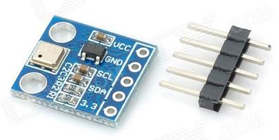
The pressure is measured by BMP180 sensor. BMP 180 Datasheet.
I bought this module: http://www.dx.com/p/bmp180-bosch-temperature-air-pressure-module-deep-blue-294251
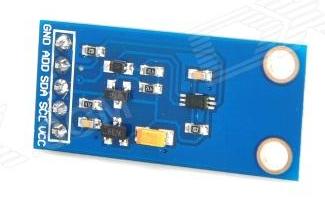
The light intensity is measured by BH1750FVI sensor. BH1750FVI Datasheet.
I bought this module: http://www.dx.com/p/bh1750fvi-digital-light-intensity-sensor-module-blue-182595
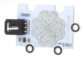
The rain status is measured by module from Octopuss. Essentially it is grad type water level sensor. I bought it here: http://www.dx.com/p/octopus-rain-steam-sensor-module-w-cable-white-silver-192829
It is connected to AD converter.
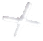
I bought polyethylene tubes, joints etc. to connect pump, valves and pots here: http://www.instarjbc.cz and here: http://www.koupelnyeshop.cz/ .
Valve with connections for polyethylene tube:
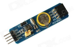
Real time clock module keeps time in the case of boot up without internet. It is based on the chip PCF8563. Module Datasheet, PCF8563 Datasheet.
I bought it here: http://www.dx.com/p/pcf8563-rtc-board-for-raspberry-pi-real-time-clock-module-blue-281614
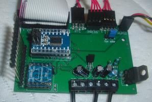
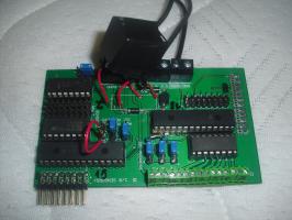
This is electronics to interface power source, water pump, water level and weather sensors to the Raspberry Pi. Generally it transform voltage levels and connects sensors, analogue to digital converters and port expander to the Raspberry Pi.
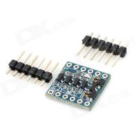
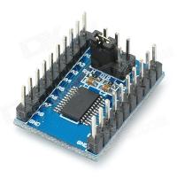
Main board contains connector to Raspberry Pi, connectors for weather sensors (all but rain sensor), RTC, voltage stabilizer to generate water pump voltage, bidirectional voltage converter and unidirectional voltage converter. Raspberry Pi works with 3.3 V logic level. To convert logic to 5 V, bidirectional level converter JY-MCU is used for I2C bus. It can convert only four wires, therefore it is used only for wires where bidirectionality is required. For the rest a unidirectional voltage converter with 74LVC8T245 chip was used.
The secondary board contains two port expanders MCP23017, one AD converters MCP3008 for mesurement of grad sensors value, two transistor arrays ULN2003A and one relay. One transistor array is connected to 24 V and one port expander. It is used to switch valves. Second transistor array is connected to 5 V and second port expander. It is used to switch grad sensors (why it is needed see grad sensors hardware). Rest of pins of port expanders are used for binary water level sensors. AD converter is used to read value of gradual water level sensors. A relay is used to switch water pump.
Multiple secondary boards can be (theoretically, not tested) connected and stacked. One have to ensure all I2C addresses of port expanders and sensors and SPI cable select wires are different on all boards.
I used JY-MCU 5V 3V IIC UART SPI Level 4-Way Converter Module Adapter from http://www.dx.com/p/74lvc8t245-8-ch-ttl-coms-level-conversion-module-deep-blue-286606. It is based on 4 MOSFETs. A lot of other similar boards can be found.
I used 74LVC8T245 8-CH TTL COMS Level Conversion Module from http://www.dx.com/p/74lvc8t245-8-ch-ttl-coms-level-conversion-module-deep-blue-286606. It is based on chip 74LVC8T245. Level conversion direction is set by a jumper.
MCP23017 has 16 I/O ports and is controlled by I2C bus. Datasheet.
MCP3008 is 10-bit 8 channel AD converter and is controlled by SPI bus. Datasheet.
ULN2003A has 7 darlington transistors. It is controlled directly by TTL signal. It is used for binary water level sensors and power to the gradual sensors. (It would be probably better to use TD62783 chip, maybe in next revision...) Datasheet.
Software is documented by doxygen. It is running in two threads. Main thread does watering, timing, data saving and loading etc. Second thread serve as a web server, and can set flags for first thread. Main thread reacts to these flags when possible (not immediately).
Main thread runs in loops, time length of the loop can be set by user (e.g. one hour). At the beginning of the loop software first measures water levels and values of other sensors. Next it determines if watering of some pot should start. If so, it waters pots. Than it waits for next iteration of the loop.
Software can be controlled by the user by means of a web page.
Watering is driven by programs. Three types of programs are used:
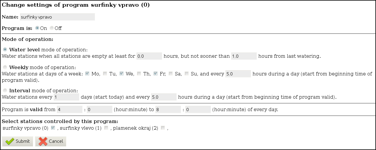
- Water level mode of operation.
- Weekly mode of operation.
- Interval mode of operation.
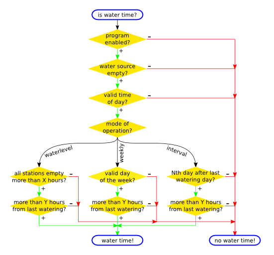
First one waters only if station is empty at least for specified amount of time, and not sooner than specified amount of time from last watering. Usefull when watering should be driven by water level with some binary water level sensors or by soil humidity, if gradual water level sensor is assigned.
Second type of program waters only at specified days of week, and every specified amount of time during the day. Usefull for watering lawns every weekend. If water level sensor is assigned, the watering runs only if water level is measured as zero (empty).
Third type of program is the same as second, but the day is specified by interval of days. I.e. if interval is 2 days, every second day watering will start. It means at first week it will be on Monday, Wednesday, Friday, Sunday, then second week on Tuesday, Thursday, Sunday and third week again Monday etc.
For every program valid time during day can be specified. The program will commence only in specified time of day.
To every program one or more stations must be assigned.
Program can be switched on or off.
Any number of programs can be created.
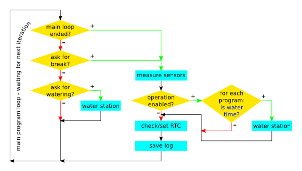
For a basic operation scheme of a main thread, see following figure:
If user asks for Check now on home page, waiting for next main loop iteration is ended. If user asks for watering of particular station from stations webpage, main loop is paused and station is watered. Than main loop continues as usually.
If station should be watered is based on sensors and settings. See following figure for an algorithm:
Main part of software is in yawspi.py. After startup the run is divided into two threads. To test the system, run following on a PC (not in Raspberry Pi) in yawspisw directory:
python yawspi.py
Now the system will run in demo mode with demo hardware configuration. Take a look at webpage on address http://127.0.0.1:8080, you should see a home page.
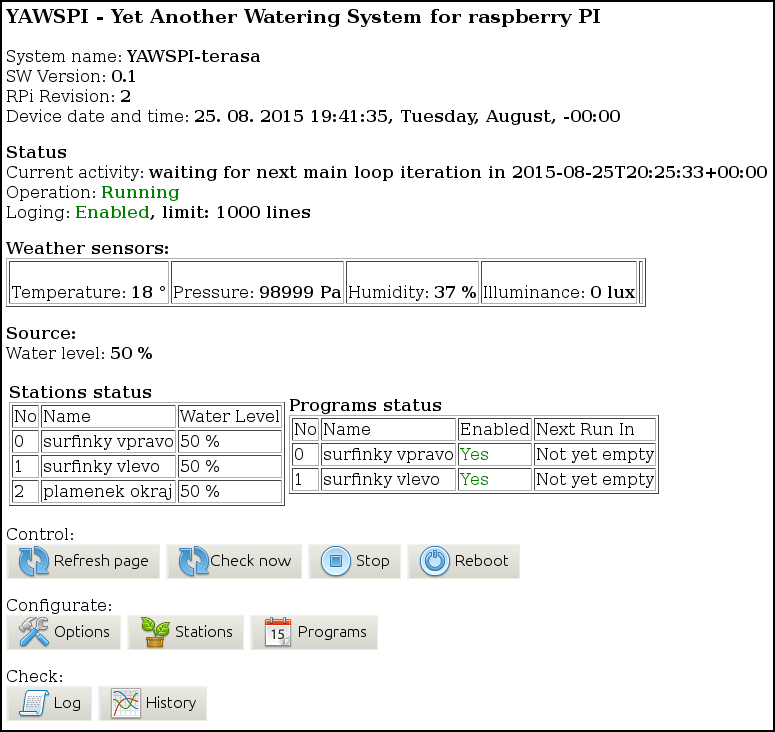
Home page shows basic status of the hardware.
Button Refresh page just reloads this page. Button Check now asks the main thread to break waiting loop and to measure water levels now and commence any watering if needed. Button Stop/Start stops or starts the operation - it means sensors are measured, but all watering programs are not working. You can reboot the Raspberry Pi by Reboot button.
Buttons at the bottom of the page leads to other web pages.
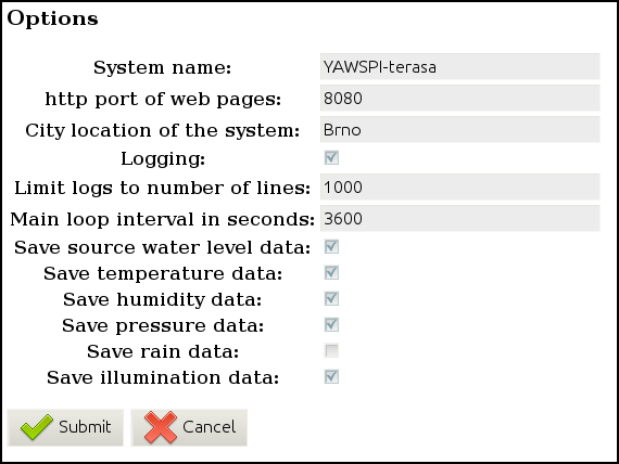
Several settings related to general system can be setup on this web page.
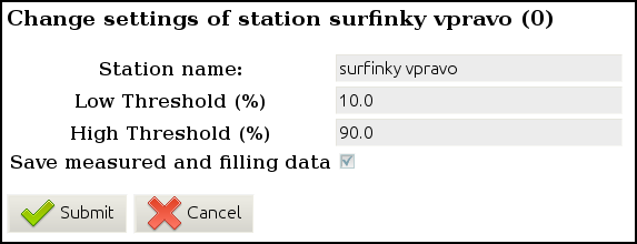
All stations (defined by hw_settings.py) are listed here. By pressing button Water now this station will be filled by water independently on the watering program. Settings for particular station can by changed by pressing button Edit. Settings are:
- Station name - user defined name of the station.
- Low threshold (%) - if sensor reports water level below this value, the value is considered as zero.
- High threshold (%) - if sensor reports water level over this value, the value is considered as 100%.
- Save measured and filling data - systems saves water level measurements and data about water filling to a separate file, thus history can be showed in the chart.
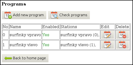
New programs can be added here or programs can be deleted. By pressing button Check programs, a list of watering times of active watering programs for next 14 days is shown. Watering programs with water level mode of operation are omitted, because they are not driven primarily by date and time. Pressing button Edit program shows a web page with settings for the particular program.
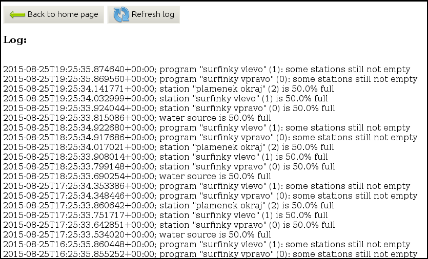
Log of the system is shown from newest messages to oldest ones. This is useful for determining problems.
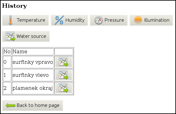
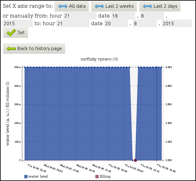
A chart of history of stations or weather sensors can be shown. Data are shown only if saving of particular sensor is switched in options web page or saving of particular stations is switched in stations web page.
The hw_control.py module serve as abstraction layer.
Python modules for hardware were copied from http://www.adafruit.com/, from http://www.astromik.org/malymenu/menuraspi.htm or written by myself. List of modules:
- Adafruit_I2C.py
- Adafruit_MCP230XX.py
- BH1750.py
- BMP180.py
- DHT11.py
- MCP3008.py
- rtc8563.py
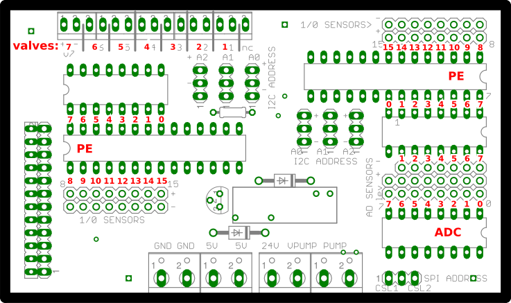
Configuration of the hardware is written in hw_config.py. If the software is not run on raspberry, hw_config_demo.py is used. Because theoretically more secondary boards can be connected, there is used a simple syntax for pin numbering. Every pin is composed of tuple of two numbers. First number determines device - GPIO of Rapsberry Pi is 0, first port expander is 1, second is 2 etc. First AD converter is -1, second is -2 etc. Second number is a pin on the device itself. For example, fifth IO pin on second port expander is written as (2, 4), because pins are numbered from zero in python modules and datasheets. To help find out where is what connected, following figure can be used.
In the configuration is written complete setup of the hardware. Please see hw_config_demo.py for explained and fully described example.
For every water station (pot) there is dedicated one valve and one software water level sensor (which can be composed of several hardware water level sensors).
Hardware water level sensors are represented in the software as one of these types:
- none
- min
- max
- minmax
- grad
This software representations can take data from zero, one or two hardware water level sensors. Other types can be implemented by modifying hardware abstraction layer. Final output of every sensor is between 0 (empty) to 1 (full). User can setup low and high thresholds. For example if output of sensor is below low threshold, output is considered as zero. This is to prevent measurement noise.
No water level sensor. Software always assume the water pot is always empty. Amount of water needed to water the pot is determined by the water capacity of the water pot.
Sensor changes state when water level reaches the bottom of the water pot. Sensor detects water pot is empty, otherwise software assume water pot is 50% full. Amount of water needed to water the pot is determined by the water capacity of the water pot. For this one binary water level sensor placed at the bottom of pot is needed.
Sensor changes state when water level reaches the top of the water pot. Sensor detects water pot is full, otherwise software assume water pot is 50% full. Amount of water needed to water the pot is determined by the sensor. For this one binary water level sensor placed at the top of pot is needed.
Sensor changes state when water level reaches the top or the bottom of the water pot. Sensor detects water pot is full, empty or 50%. Amount of water needed to water the pot is determined by the sensor. For this two binary sensors are needed, one placed at the bottom, second at the top of the pot.
Analog sensor. Sensor directly detects the water level. Amount of water needed to water the pot is determined by the sensor. For this one gradual water sensor is needed.
