Also make sure to check out the original msdfgen project which this project is based on
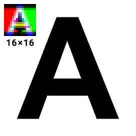
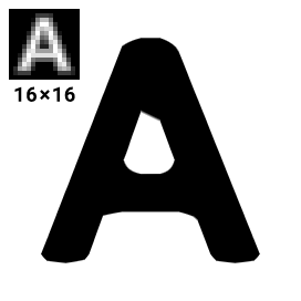
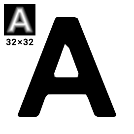
This is a utility for generating signed distance fields from vector shapes and font glyphs, which serve as a texture representation that can be used in real-time graphics to efficiently reproduce said shapes. Although it can also be used to generate conventional signed distance fields best known from this Valve paper and perpendicular distance fields, its primary purpose is to generate multi-channel distance fields, using a method I have developed. Unlike monochrome distance fields, they have the ability to reproduce sharp corners almost perfectly by utilizing all three color channels.
The following comparison demonstrates the improvement in image quality.
- To learn more about this method, you can read Chlumsky's Master's thesis.
- See what's new in the changelog.
If you choose to use this utility inside your own program, there are a few simple steps you need to perform
in order to generate a distance field. Please note that all classes and functions are in the msdfgen namespace.
- Acquire a
Shapeobject. You can either load it vialoadGlyphorloadSvgShape, or construct it manually. It consists of closed contours, which in turn consist of edges. An edge is represented by aLinearEdge,QuadraticEdge, orCubicEdge. You can construct them from two endpoints and 0 to 2 Bézier control points. - Normalize the shape using its
normalizemethod and assign colors to edges if you need a multi-channel SDF. This can be performed automatically using theedgeColoringSimple(or other) heuristic, or manually by setting each edge'scolormember. Keep in mind that at least two color channels must be turned on in each edge. - Call
generateSDF,generatePSDF,generateMSDF, orgenerateMTSDFto generate a distance field into a floating pointBitmapobject. This can then be worked with further or saved to a file usingsaveBmp,savePng, orsaveTiff. - You may also render an image from the distance field using
renderSDF. Consider callingsimulate8biton the distance field beforehand to simulate the standard 8 bits/channel image format.
Example using the C++ API:
#include <msdfgen.h>
#include <msdfgen-ext.h>

using namespace msdfgen;

int main() {
    FreetypeHandle *ft = initializeFreetype();
    if (ft) {
        FontHandle *font = loadFont(ft, "C:\\Windows\\Fonts\\arialbd.ttf");
        if (font) {
            Shape shape;
            if (loadGlyph(shape, font, 'A')) {
                shape.normalize();
                //                      max. angle
                edgeColoringSimple(shape, 3.0);
                //          output width, height
                Bitmap<float, 3> msdf(32, 32);
                //                           scale, translation
                SDFTransformation t(Projection(1.0, Vector2(4.0, 4.0)), Range(4.0));
                generateMSDF(msdf, shape, t);
                savePng(msdf, "output.png");
            }
            destroyFont(font);
        }
        deinitializeFreetype(ft);
    }
    return 0;
}
Example using the C API:
#include <msdfgen_c.h>

int main(int num_args, char** args) {
    msdf_bitmap_t bitmap;
    if(msdf_bitmap_alloc(MSDF_BITMAP_TYPE_MSDF, 16, 16, &bitmap) != MSDF_SUCCESS) {
        return 1;
    }
    msdf_shape_handle shape = NULL;
    if(msdf_shape_alloc(&shape) != MSDF_SUCCESS) {
        return; // Handle error accordingly
    }
    // Create shape data from font using FreeType, STB etc here..
    msdf_transform_t transform;
    transform.scale.x = 1.0;
    transform.scale.y = 1.0;
    transform.translation.x = 4.0;
    transform.translation.y = 4.0;
    transform.distance_mapping.lower = 4.0;
    transform.distance_mapping.upper = 4.0;
    if(msdf_generate_msdf(&bitmap, shape, &transform) != MSDF_SUCCESS) {
        return 1;
    }
    // DO SOMETHING WITH THE GENERATED GLYPH BITMAP HERE..
    // Make sure to free heap allocated resources when we're done
    msdf_shape_free(shape);
    msdf_bitmap_free(&bitmap);
    return 0;
}
Using a multi-channel distance field generated by this program is similarly simple to how a monochrome distance field is used. The only additional operation is computing the median of the three channels inside the fragment shader, right after sampling the distance field. This signed distance value can then be used the same way as usual.
The following is an example GLSL fragment shader with anti-aliasing:
in vec2 texCoord;
out vec4 color;
uniform sampler2D msdf;
uniform vec4 bgColor;
uniform vec4 fgColor;

float median(float r, float g, float b) {
    return max(min(r, g), min(max(r, g), b));
}

void main() {
    vec3 msd = texture(msdf, texCoord).rgb;
    float sd = median(msd.r, msd.g, msd.b);
    float screenPxDistance = screenPxRange()*(sd - 0.5);
    float opacity = clamp(screenPxDistance + 0.5, 0.0, 1.0);
    color = mix(bgColor, fgColor, opacity);
}
Here, screenPxRange() represents the distance field range in output screen pixels. For example, if the pixel range was set to 2
when generating a 32x32 distance field, and it is used to draw a quad that is 72x72 pixels on the screen,
it should return 4.5 (because 72/32 * 2 = 4.5).
For 2D rendering, this can generally be replaced by a precomputed uniform value.
For rendering in a 3D perspective only, where the texture scale varies across the screen,
you may want to implement this function with fragment derivatives in the following way.
I would suggest precomputing unitRange as a uniform variable instead of pxRange for better performance.
uniform float pxRange; // set to distance field's pixel range

float screenPxRange() {
    vec2 unitRange = vec2(pxRange)/vec2(textureSize(msdf, 0));
    vec2 screenTexSize = vec2(1.0)/fwidth(texCoord);
    return max(0.5*dot(unitRange, screenTexSize), 1.0);
}
screenPxRange() must never be lower than 1. If it is lower than 2, there is a high probability that the anti-aliasing will fail
and you may want to re-generate your distance field with a wider range.
The text shape description has the following syntax.
- Each closed contour is enclosed by braces:
{ <contour 1> } { <contour 2> } - Each point (and control point) is written as two real numbers separated by a comma.
- Points in a contour are separated with semicolons.
- The last point of each contour must be equal to the first, or the symbol
#can be used, which represents the first point. - There can be an edge segment specification between any two points, also separated by semicolons.
This can include the edge's color (
c,m,yorw) and/or one or two Bézier curve control points inside parentheses.
For example,
{ -1, -1; m; -1, +1; y; +1, +1; m; +1, -1; y; # }
would represent a square with magenta and yellow edges,
{ 0, 1; (+1.6, -0.8; -1.6, -0.8); # }
is a teardrop shape formed by a single cubic Bézier curve.