The 8375 Agnus needed for Amiga 500+ is getting expensive and scarce so this adapter is designed to allow you to fit the much more common 8372A and other 1MB Agnuses from the A500 It also has the ability to take 1MB of DRAM on board instead of the harder to source DIP20 DRAMs needed for an Amiga
PCBs are available at Bobs Bits
Q. Will this give me 2MB chip ram?
A. No, the 8372 Agnus supports a maximum of 1MB chip ram
Q. Does my Amiga need any ram chips on-board?
A. If you fit the RAM chips specified to the Diet Agnus adapter then your mainboard needs no working chip ram (So if you're building an A500++ you can leave those out)

-
Solder the DRAMs (or if using the Amiga's ram, cut and set the jumpers to "Enabled" and go to step 3)
-
Solder the Capacitors (Only fit VBB capacitor if your Agnus says VBB on the top)
-
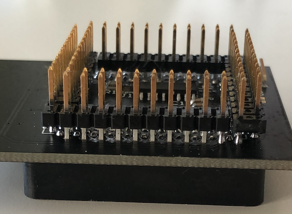
Solder the PLCC Socket making sure that the socket aligns exactly with the outline on the top of the PCB!
-
After soldering the socket, you may want to trim the joints down to the PCB to make soldering the pin headers easier.
Be careful when trimming the leads that you don't scratch the PCB solder mask! -
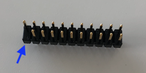
Prepare the pin headers by removing a pin from this corner of each as indicated here:

-
Insert one of the pin headers just far enough for it to hold, making sure that it is level.
The side with the removed pin goes where indicated by the yellow arrow
I recommend doing them one by one in the order indicated:
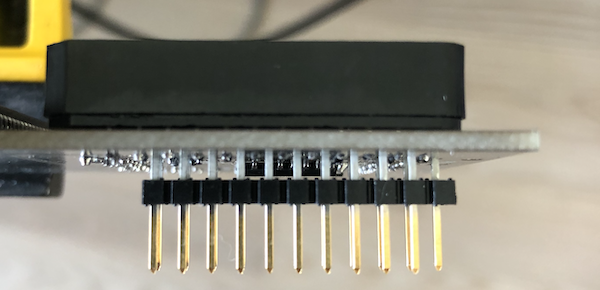
If you will be soldering to the Amiga rather than using sockets, I would recommend soldering the long side of the pins to the adapter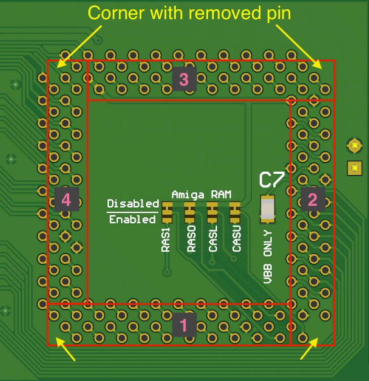

-
Solder in each pin, don't use too much solder!
-
Repeat for each pin header


You will need to remove the Agnus socket from your Amiga PCB and solder female pin headers in it's place (making sure to remove the corner pins of the pin header) or solder direct in place of the Agnus socket.
The board must be oriented so that the RAM sits to the right of Agnus, with Agnus' pin 1 pointing to the right
Close the NTSC jumper to set your Agnus to NTSC mode (Only if the Agnus isn't marked with VBB!)
The "Amiga RAM" jumpers control whether the various RAM control signals are routed to the Amiga's original ram or to the ram chips on the board.
If you have fitted the 2 RAM chips to this adapter you must leave the jumpers at the default setting.
If you instead want to make use of the Amiga's RAM chips you can cut and set all 4 of the jumpers to "Enabled" and leave off the 2x ram chips.
| Component | Location | QTY | Link |
|---|---|---|---|
| Diet Agnus PCB | 1 | Bobs Bits | |
| Ceramic Capacitor, 0.1uF, 0805 | C1-7 | 7 | Mouser |
| PLCC-84 Socket, Through-hole | U1 | 1 | Mouser |
| 5V, 256Kx16 EDO/FPM DRAM, SOJ-40 (e.g HYB514171BJ) | U2-3 | 2 | eBay, Aliexpress etc |
| 22-Pin, 2 Row Female header | 4 | Mouser | |
| 22-Pin, 2 Row Male header | 4 | Mouser |