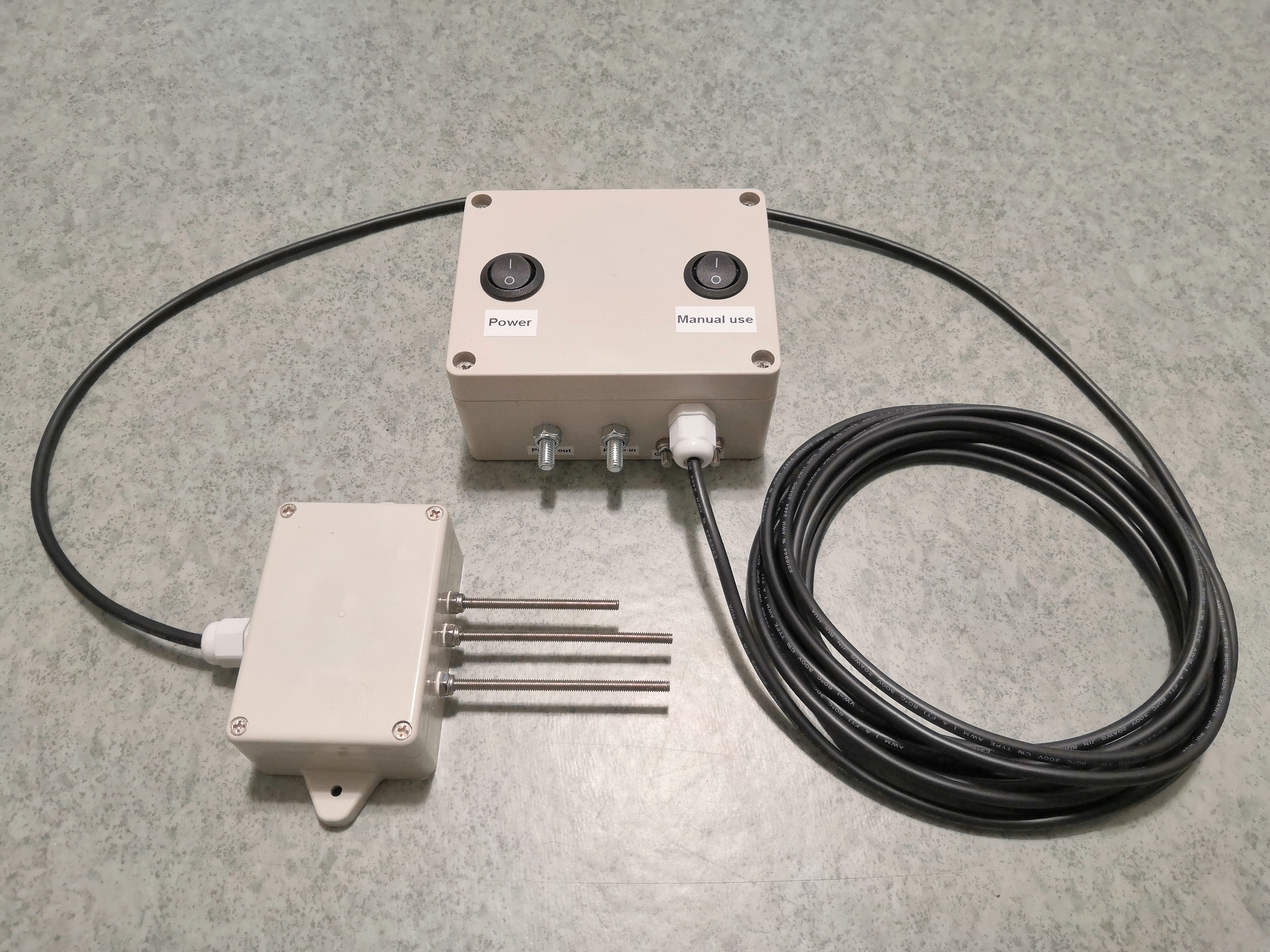
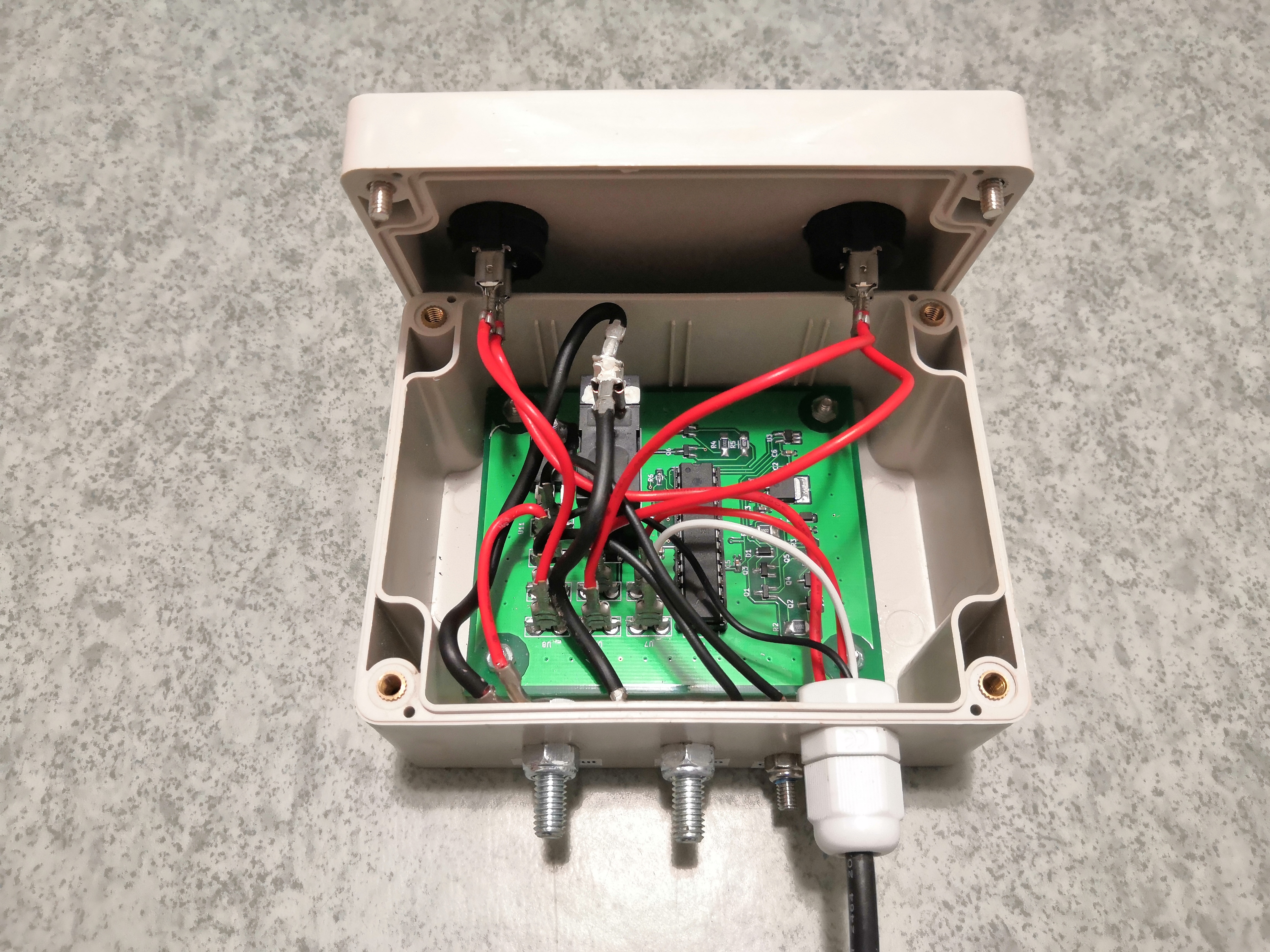
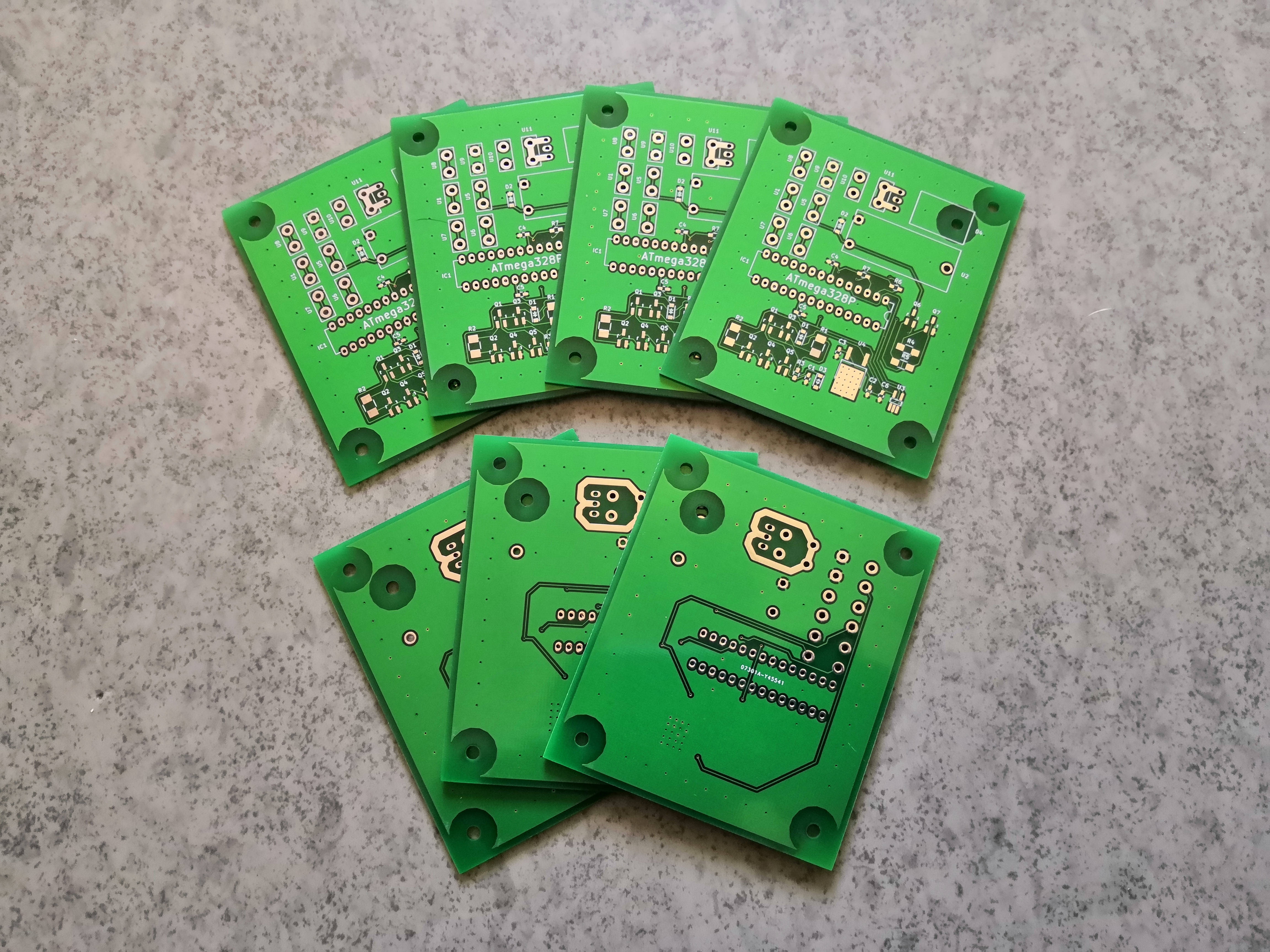
There are lots of mechanical bilge pump switches out there to cause issues for boat owners, and 'float switch' is propably most common type of a mechanical bilge pump switch. It consists from electrical switch and an floating arm. As water level rises, switch arm begins to float upwards. When it exceeds certain threshold, electrical switch closes and bilge pump turns on. And when water level and arm drops low enough, switch opens and bilge pump is turned off. Sounds simple, right? What could possibly go wrong? Well, apparently nearly everything.
This switch needs to be able to conduct enough of current to run bilge pump. If switch contacts would be closed directly by slowly floating arm, it would most likely cause lots of arcing resulting to destroyed switch contacts very quickly. One technique to overcome this is to place steel ball inside floating arm, which slams into contacts closing them when arm rises high enough. Downside of this is that steel ball tends to cause plastic casing to crack eventually. And considering that switch is right next to a water, contacts will corrode quickly leading to not-so-well functioning switch. And this should be enough of reasoning to engineer electronic bilge pump switch that is not prone to various issues seen in mechanical switches.
This project was also great exercise to learn basics of microcontrollers, as this was first project where I used one of those.
This device consists from three parts, sensor, main electronics and cable connecting those two together. Sensor is made out out stainless steel rods and plastic casing. One rod is connected to ground and second is pulled high by very weak pull-up resistor. When water level rises and connects those two rods together, weak pull-up resistor can no longer keep voltage high on that second rod. This rod is then connected to MCU and can be treated as digital input to indicate whether or not water level is above certain threshold. Hysteresis can be created by adding third rod to sensor which is placed higher than other two rods. Now higher rod can be used to detect when to turn bilge pump on and lower one when to turn bilge pump off.


