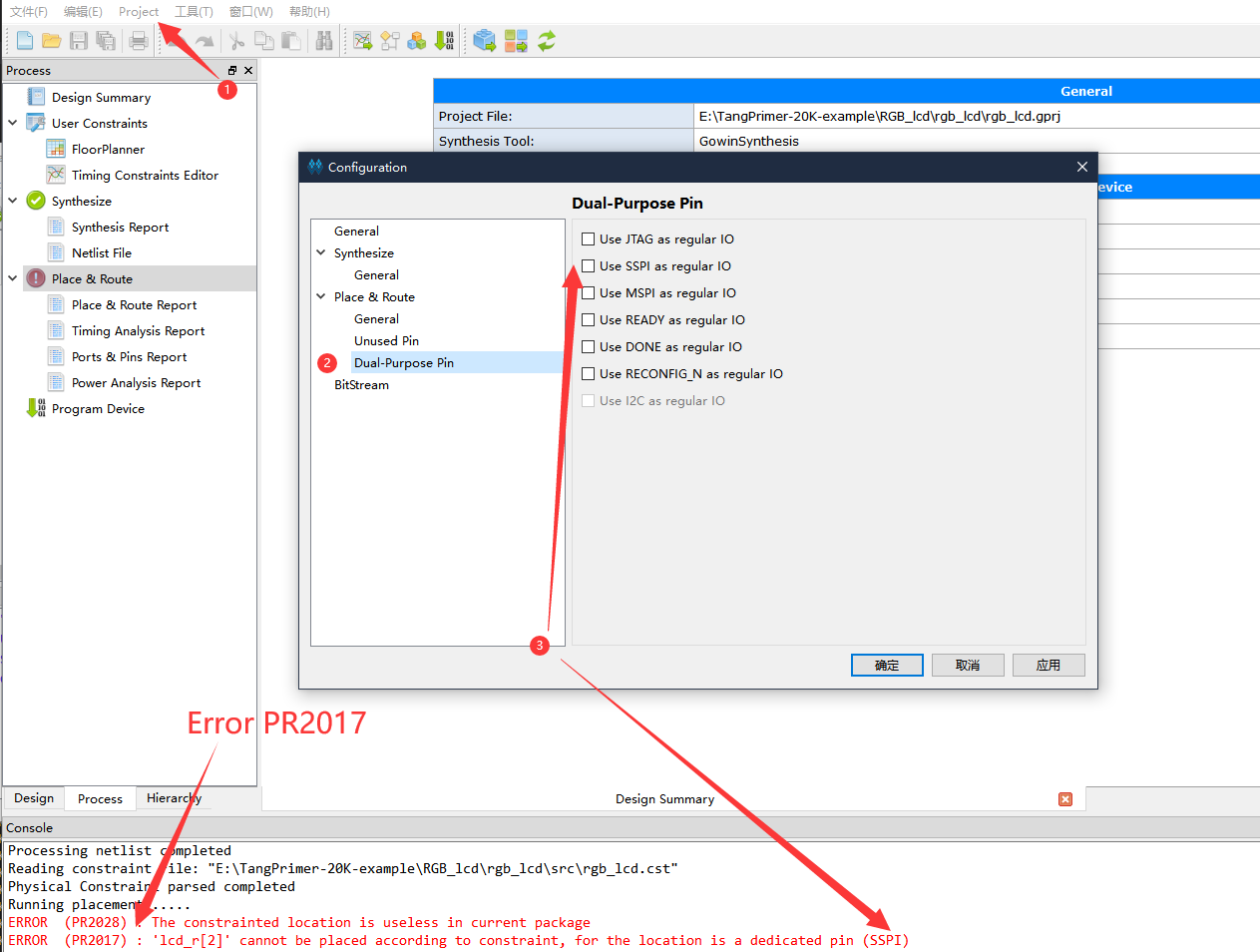
When you meet error code PR2017, just enable corresponding IO as regular IO.
Click Project in top menu bar and choose Configuration, then enable the corresponding Dual Purpose Pin to deal with this error.
This is the test project which is used for testing Lite-bottom and core board(Factory test). Including the DDR-Test project and another demo containing all other usable IO blink.
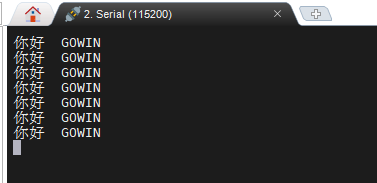
Thanks ZiyangYE providing this example. Using serial-communication with 115200 baudrates to shows result.
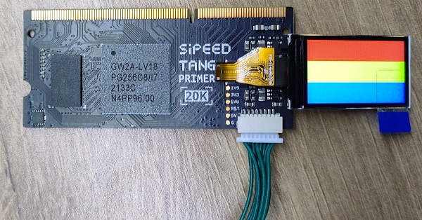
This is an example driving 1.14 inch spi screen.
Screen datasheet: Click me
Cross colorbar on the screen.
| 480x272_4.3inch_lcd | 800x480_5inch_lcd |
|---|---|
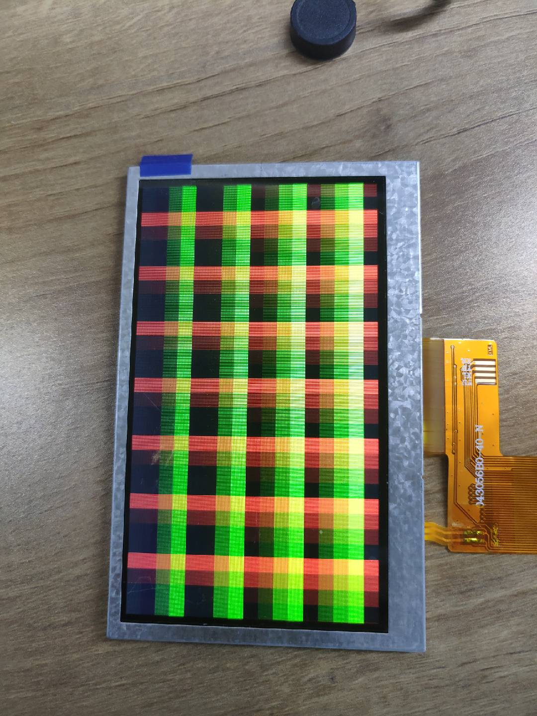 |
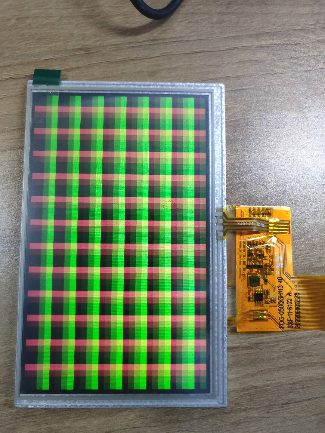 |
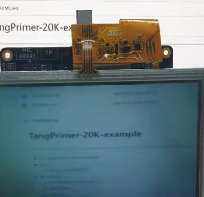
Colorbar on screen
| rgb_lcd_4.3inch_colorbar | rgb_lcd_5inch_colorbar |
|---|---|
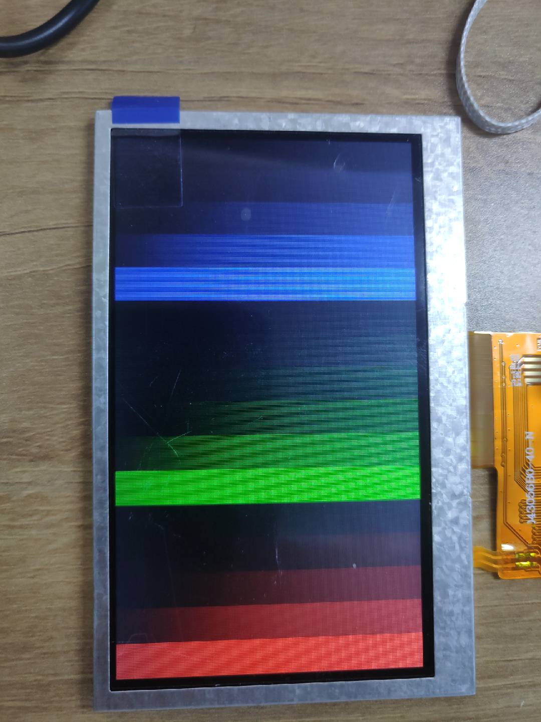 |
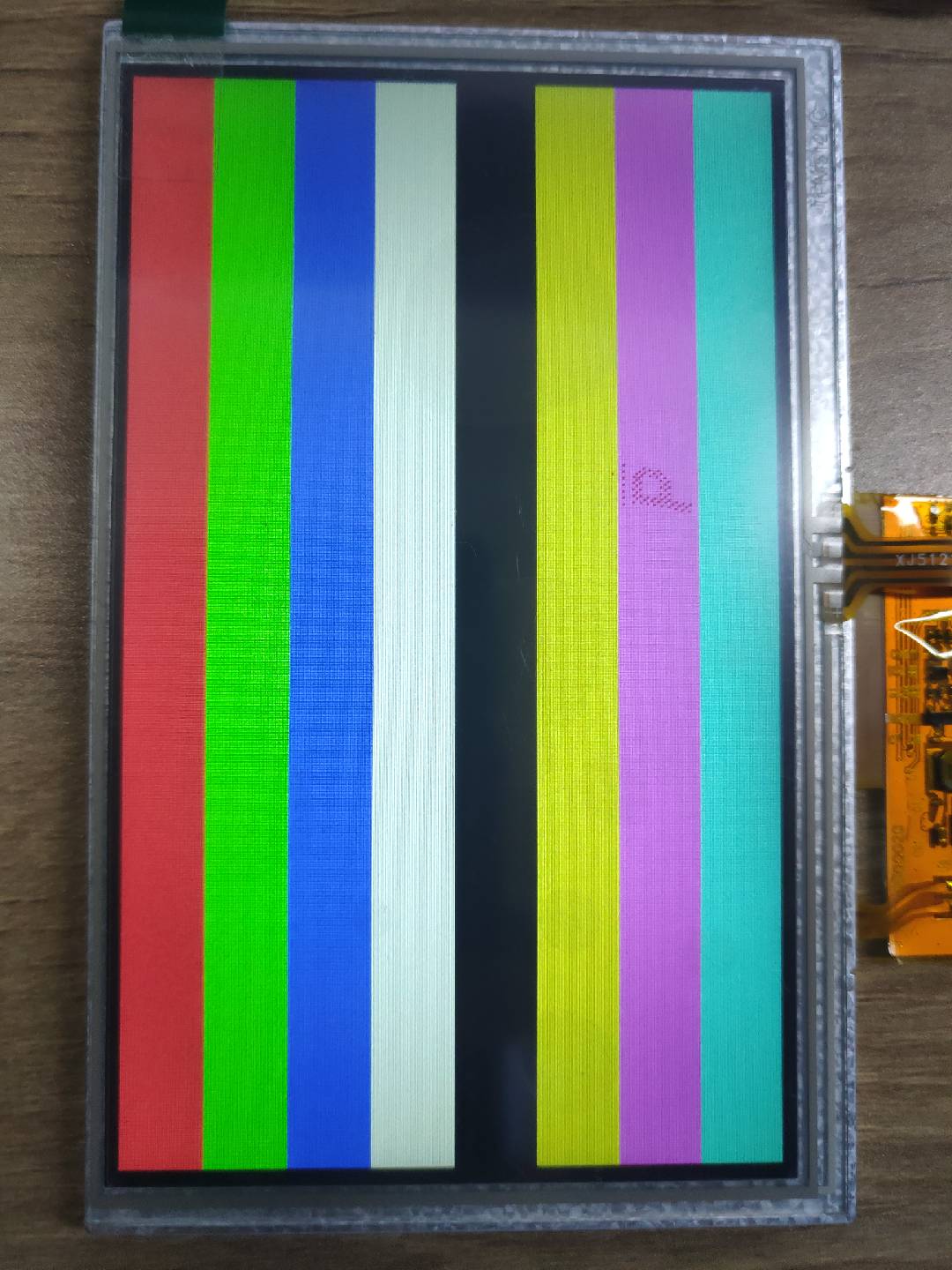 |
There are 4 projects, their name rules are as followings:
| Folder name | Camera | Screen resolution | Frame storge mode |
|---|---|---|---|
| OV5640_LCD480_DDR3 | OV5640 | 480x272 | DDR3 |
| OV5640_LCD800_DDR3 | OV5640 | 800x480 | DDR3 |
| OV5640_LCD480_FIFO | OV5640 | 480x272 | FIFO |
| OV5640_LCD800_FIFO | OV5640 | 800x480 | FIFO |
These are only for testing, and if you want better results, you need program on yourself.
After burning the .fs bitstream into fpga, press S0 button to reset fpga chip to get right display.
There is demo for micarray board.
This runs a rv32ic rocket core with a UART peripheral attached. This example system outputs A via UART infinitely.
A demo for onboard ws2812 led.
Demo for onboard USB3317 Hi-Speed USB Transceive based on LUNA.
A demo of UART, set baudrate and open the onboard COM port to see the message.
The clock pin on primer 20K is H11
The reset pin on primer 20K is T10
| PORT | IO | Pin | PORT | IO | Pin |
|---|---|---|---|---|---|
| lcd_dclk | output | R9 | lcd_de | output | E15 |
| lcd_hs | output | A15 | lcd_vs | output | D14 |
| lcd_r[0] | output | L9 | lcd_r[1] | output | N8 |
| lcd_r[2] | output | N9 | lcd_r[3] | output | N7 |
| lcd_r[4] | output | N6 | lcd_g[0] | output | D11 |
| lcd_g[1] | output | A11 | lcd_g[2] | output | B11 |
| lcd_g[3] | output | P7 | lcd_g[4] | output | R7 |
| lcd_g[5] | output | D10 | lcd_b[0] | output | B12 |
| lcd_b[1] | output | C12 | lcd_b[2] | output | B13 |
| lcd_b[3] | output | A14 | lcd_b[4] | output | B14 |
| PORT | IO | Pin | PORT | IO | Pin |
|---|---|---|---|---|---|
| cmos_scl | inout | F14 | cmos_sda | inout | F16 |
| cmos_vsync | input | G15 | cmos_href | input | G14 |
| cmos_pclk | input | F13 | cmos_xclk | output | G12 |
| cmos_rst_n | output | L13 | cmos_pwdn | output | C10 |
| cmos_db[0] | input | T12 | cmos_db[1] | input | T11 |
| cmos_db[2] | input | P11 | cmos_db[3] | input | R11 |
| cmos_db[4] | input | M15 | cmos_db[5] | input | M14 |
| cmos_db[6] | input | J16 | cmos_db[7] | input | J14 |
| PORT | IO | Pin | PORT | IO | Pin |
|---|---|---|---|---|---|
| ulpi_stp | output | K11 | ulpi_rst | output | F10 |
| ulpi_data[7] | inout | R12 | ulpi_data[6] | inout | P13 |
| ulpi_data[5] | inout | R13 | ulpi_data[4] | inout | T14 |
| ulpi_data[3] | inout | H13 | ulpi_data[2] | inout | J12 |
| ulpi_data[1] | inout | H12 | ulpi_data[0] | inout | G11 |
| ulpi_nxt | input | K13 | ulpi_dir | input | K12 |
| ulpi_clk | input | T15 | rst_n | input | T3 |
| PORT | IO | Pin | PORT | IO | Pin |
|---|---|---|---|---|---|
| ddr_bank[0] | output | H4 | ddr_bank[1] | output | D3 |
| ddr_bank[2] | output | H5 | ddr_odt | output | R3 |
| ddr_addr[0] | output | F7 | ddr_addr[1] | output | A4 |
| ddr_addr[2] | output | D6 | ddr_addr[3] | output | F8 |
| ddr_addr[4] | output | C4 | ddr_addr[5] | output | E6 |
| ddr_addr[6] | output | B1 | ddr_addr[7] | output | D8 |
| ddr_addr[8] | output | A5 | ddr_addr[9] | output | F9 |
| ddr_addr[10] | output | K3 | ddr_addr[11] | output | B7 |
| ddr_addr[12] | output | A3 | ddr_addr[13] | output | C8 |
| ddr_cke | output | J2 | ddr_we | output | L2 |
| ddr_cas | output | R6 | ddr_ras | output | R4 |
| ddr_dm[0] | output | G1 | ddr_dm[1] | output | K5 |
| ddr_ck | output | J1,J3 | ddr_reset_n | output | B9 |
| ddr_dqs[0] | inout | G2,G3 | ddr_dqs[1] | inout | J5,K6 |
| ddr_dq[0] | inout | G5 | ddr_dq[1] | inout | F5 |
| ddr_dq[2] | inout | F4 | ddr_dq[3] | inout | F3 |
| ddr_dq[4] | inout | E2 | ddr_dq[5] | inout | C1 |
| ddr_dq[6] | inout | E1 | ddr_dq[7] | inout | B3 |
| ddr_dq[8] | inout | M3 | ddr_dq[9] | inout | K4 |
| ddr_dq[10] | inout | N2 | ddr_dq[11] | inout | L1 |
| ddr_dq[12] | inout | P4 | ddr_dq[13] | inout | H3 |
| ddr_dq[14] | inout | R1 | ddr_dq[15] | inout | M2 |
| ddr_cs | output | P5 |
| PORT | IO | Pin | PORT | IO | Pin |
|---|---|---|---|---|---|
| lcd_bl | output | P12 | lcd_data | output | L15 |
| lcd_rs | output | J13 | lcd_cs | output | C16 |
| lcd_clk | output | F12 | lcd_resetn | output | G13 |
| PORT | IO | Pin | PORT | IO | Pin |
|---|---|---|---|---|---|
| uart_tx | output | M11 | uart_rx | input | T13 |
| PORT | IO | Pin | PORT | IO | Pin |
|---|---|---|---|---|---|
| CLK | output | N10 | CMD | input | R14 |
| DAT0 | inout | M8 | DAT1 | inout | M7 |
| DAT2 | inout | M10 | DAT3 | inout | N11 |
| DET_A | input | D15 |
