If you're reading this it's likely because you've noticed that your MK4 xBuddy Controller has a port reserved for an accelerometer and wondered "Hmmm. I wonder if that works."
I'm happy to report that the answer is "Yes." I found it to be reliable and working just fine, but in response to my demo, Josef Prusa himself responded "Hi! Please note the code is not tested on MK4 so you shouldn't count on it's results. There will be an official implementation but not ETA yet." Source here.
This repository contains information, designs, and tools for using an accelerometer with the Prusa MK4 3D Printer.
This primary document is focused on being a quick start guide, while other documents in the repository contain more in-depth technical information about other aspects of the project.
Here's a roadmap of a few simple tasks that I'd like to accomplish with this project.
- Design mounts for the Toolhead and Bed that work with both custom and off the shelf boards.
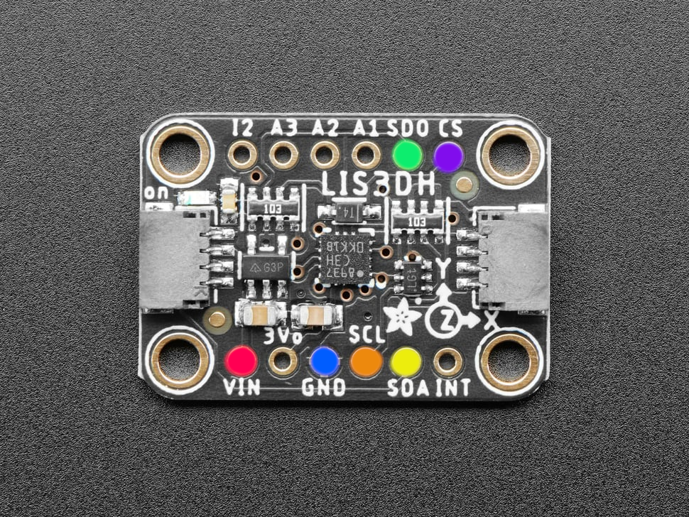
- Test other chips like the LIS3DH for compatibility.
- Run print tests and document outcomes (IN PROGRESS)
- Design our own custom PCB with a compatible Molex Clik-MATE connector (IN PROGRESS-Design Complete, Validation Underway)
- This will allow users to install an accelerometer quickly and without all the tools needed to solder.
- At the moment, only MCDELTAT has confirmed the accelerometer as working on firmware versions 5.2.1 and 6.0.0. Their printer uses the 2021 0.2.7 xBuddy board. Two other community members have tried on printers that use the 0.3.7 board and are not seeing similar signals on their ports. I'm working with them and hoping Prusa will release the older schematics so I can compare.
Q: Does this void my warranty?
A: Probably.
You can read the official Prusa Warranty on their website here. Quote "This warranty is voided by: ... Upgrades or add-ons that are not officially supported."
This modification does not require you to compile or upload any custom firmware to work. The release firmware directly from Prusa supports these boards, so this is purely a hardware addition. That said, I will include thorough warnings where appropriate to ensure that nothing goes wrong, should you follow the instructions correctly.
Here is a list of tools that will be needed to add an accelerometer board at the moment.
- Clik-MATE 6 Pin Cable Assembly (MPN: 0151350606 for 600mm). Digikey source
- LIS2DH Accelerometer board ready for SPI communication.
- See the table below for a table of boards that have been tested and verified as working.
- Soldering Iron and related tools.
- (Optional) A multimeter will be helpful.
- Mounts for the board. 3D Printable mounts for the X and Y-Axis can be found here. The mounts are designed for MK4 printers, but the mounting tray is designed to be modular. At the moment the only tray is for the generic accelerometer boards. I will provide another tray for my custom board later.
- Some kind of computer capable of controlling your MK4 Printer and a USB-C Cable. I tested everything with a Raspberry Pi running Octoprint, but any compatible software should be functional. For example, Mainsail or Pronterface should be more than capable.
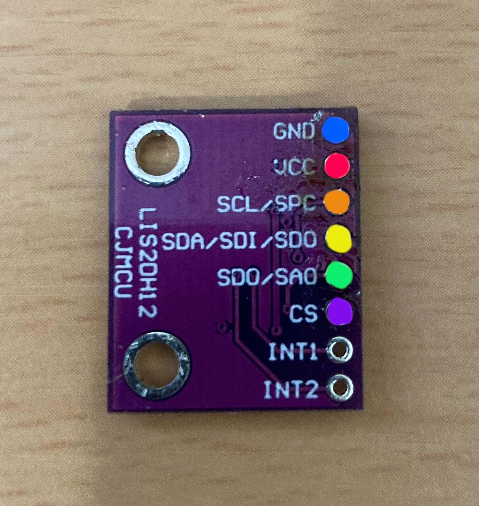
For this section, I will document the soldering procedure for the generic purple Chinese LIS2DH boards, as that is the first board I confirmed to be working.
-
Power off your printer. Unplug it from it's power source.
-
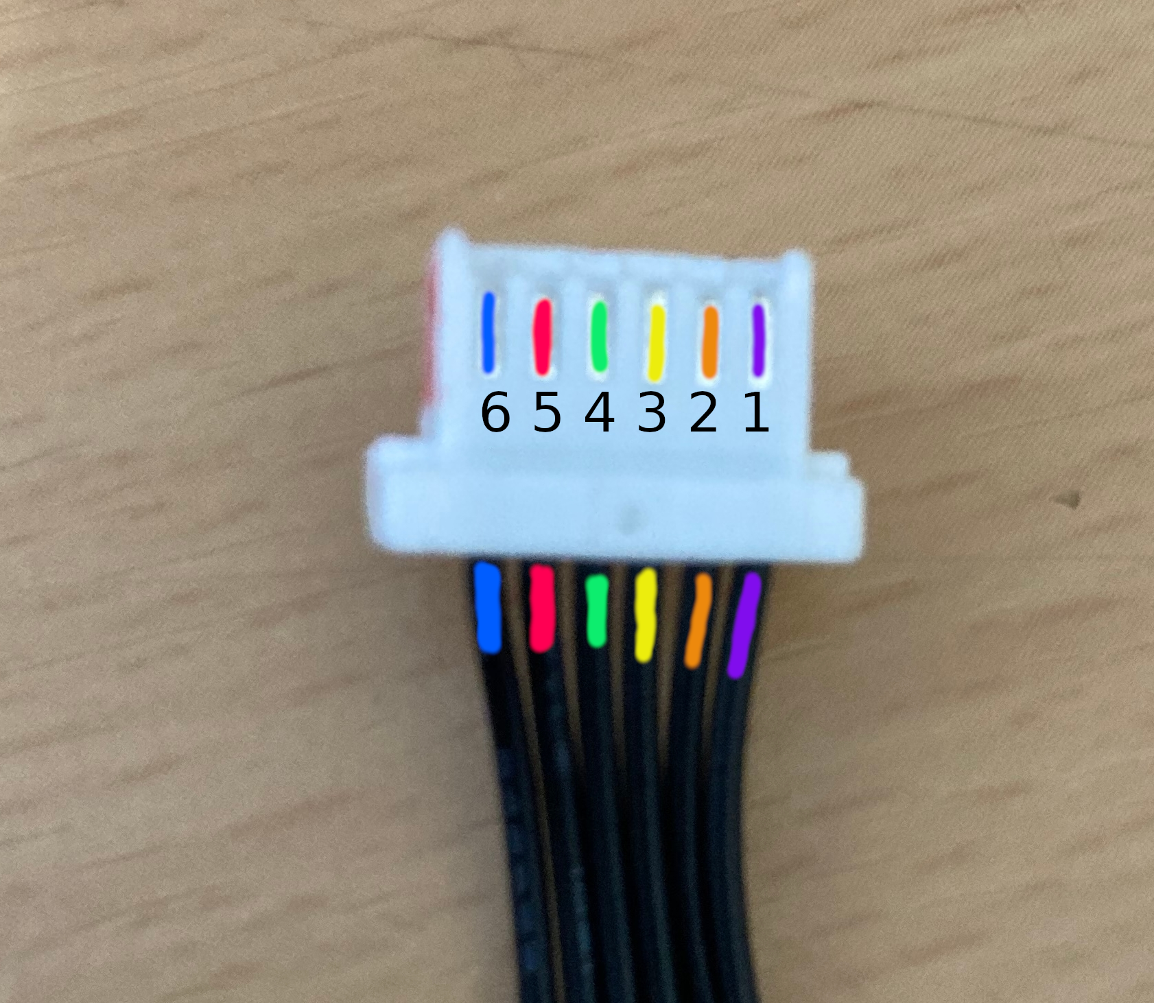
(Optional but recommended). Insert one end of your cable assembly into the Accelerometer port of the board. The connector is keyed and will only fit one direction, with the release arm facing towards the center of the board (back of the printer). Pull it back out and use a marker to color the top side of the connector. This will help you to keep track of which pin belongs to each cable.
-
Cut the cable assembly with a wire stripper or other tool. Goodbye beautiful connector.
-
Strip off approximately 5mm of the outer wire insulator for each cable.
-
(Optional tinning technique). Heat up your soldering iron, twist the stranded wires of a single cable together tightly, and apply solder to the wires. This makes it into one solid connector and makes it easier to solder to the accelerometer board later.
-
Identify the first wire to solder. If you did step two, the top side that you marked is pin 6 on the Prusa Schematics and Connector documentation. (See the Diagram below). On the Digikey cable assembly, they use tape in the middle of the cables to group them to together. We have two options:
a) Cut the tape and visually trace the cables.
b) Leave the tape intact and use a multimeter to buzz out which cable is connected to each connector pin. This can be done by switching to continuity mode, touching one lead to a cable of your choice, and the other to small pad on the back of the connector.
-
Solder the wire to the correct position. Repeat steps 5 and 6, finding the correct wires and soldering them to the board. A table is provided below for reference.
-
Snip the extra wire that wasn't covered by the solder joint.
Here is a reference table for the Prusa Connector Pins and the breakout board. Prusa's documentation supporting this is found here.
| Connector | Pin (Prusa) | Pin (Accel Board) | Type | Function | GPIO | Limitations |
|---|---|---|---|---|---|---|
| J29 (ACCELEROMETER) | 1 | CS | open drain output | SPI2 CS | PA10 | Max 3.3V/5mA |
| J29 (ACCELEROMETER) | 2 | SCL | input/output | SPI2 SCL | PB10 | Max 5V/5mA |
| J29 (ACCELEROMETER) | 3 | SDA | input/output | SPI2 SDI | PC3 | Max 5V/5mA |
| J29 (ACCELEROMETER) | 4 | SDO | input/output | SPI2 SDO | PC2 | Max 5V/5mA |
| J29 (ACCELEROMETER) | 5 | VCC | 3V3 | Power | x | Max 50mA |
| J29 (ACCELEROMETER) | 6 | GND | GND | Power | x | x |
| Board Name | Testing Status | Source | Notes |
|---|---|---|---|
| NOYITO LIS2DH12TR Development Board | WORKING | https://a.co/d/4UiPgB6 | This board is very generic and can be found many places ranging from $4 to $13. They likely all come from the same place. |
| Sparkfun SPX-15760 LIS2DH12 (Qwiic) | FAIL | https://www.sparkfun.com/products/retired/15760 | This board is hard wired for I2C, while the Prusa MK4 expects an SPI compatible device, so this will not work. |
| Adafruit LIS3DH Triple-Axis Accelerometer (Recommended) | WORKING | https://www.adafruit.com/product/2809 | The LIS3DH has a few more features we won't be using, however I confirmed it to work similarly. Since Adafruit has a solid supply chain, this is likely the best all around choice. Minor Con: The breakout board has pins on both sides, requiring cables to be on both sides, so it is a little messier. |
If you are hoping to get useful values out of the accelerometer, emphasize doing any pending maintenance first. Lube the smooth rods/bearings. Check for scratches. Check belt tension, etc. Each of these factors will change these results if you fix them later, so just do them now to avoid retesting. See Prusa's official docs for recommended regular maintenance here.
- Once you are confident your connections are going to the correct pins, plug the accelerometer into the MK4 Buddy board and the mounts.
- Connect to the printer over USB-C to issue GCODE.
⚠️ IMPORTANT STEP Before setting any parameters, gather the values that Prusa originally set on the printer. This will allow you to roll back to those values later if you want. In a GCODE control window, issue theM593command with no arguments. This will return the existing Input Shaping (IS) parameters. An example of my output can be found below. If you want to see all my Input Shaping testing results, see Testing.
Send: M593
Recv: echo:axis X type=MZV freq=50.700001 damp=0.100000 vr=20.000000
Recv: echo:axis Y type=MZV freq=40.599998 damp=0.100000 vr=20.000000
Recv: echo:axis Z disabled
Recv: echo:weight_adjust y freq_delta=-20.000000 mass_limit=800.000000
Recv: ok
-
Issue the following command
M959 X F40.0 G60.0 N10. This tests the X-Axis starting at 40Hz and ending at 60Hz, with a very quick sample size. The results this produces should not be used. It is provided here purely as a way to quickly test that you wired up the sensor correctly. -
Now to test the X-Axis, you likely want to run the default workflow, which is over a large frequency range and sample size.
-
The command above gave us a general range, but now we can confirm a second time by running it over a smaller range with more samples. For example, if step 5 returned a frequency of 79.0Hz, then I can test from 65 to 85Hz, at steps of 0.5Hz, with 100 Samples. This can be done with the command
M959 X F65.0 G85.0 H0.5. See below for a list of parameters to the M959 command. -
Once you are satisfied with the results and think you have a consistent number, we will save the values. See the official documentation for the
M593command here. Assuming I got the following resultsRecv: ZV shaper selected Recv: Frequency: 79.00 damping ratio: 0.17444a) To do this temporarily (until you shut off the printer), run the following command
M593 X D0.17444 F79.00 T0. Note the lack of theWparameter, the parameter to save it to the EEPROM.b) To save it permanently, run the following command
M593 X D0.17444 F79.00 T0 W.
The M959 command does all the heavy lifting in our testing. It's parameters are only listed in the source code, so I've copied them here for convenience.
/\*\*
 \* u/brief Tune input shaper
 \*
 \* - X<direction> Vibrate with X motor, start in direction 1 or -1
 \* - Y<direction> Vibrate with Y motor, start in direction 1 or -1
 \* - Z<direction> Vibrate with Z motor, start in direction 1 or -1
 \* - K           select Klipper tune algorithm
 \* - KM          select Klipper Marek modified tune algorithm
 \* - F<Hz>       Start frequency
 \* - G<Hz>       End frequency
 \* - H<Hz>       Frequency step
 \* - A<mm/s-2>   Acceleration
 \* - N<cycles>   Number of excitation signal periods
 \*               of active measurement.
 \*/


