Floating Cable Trap Design
This repository contains source and output files for a 3D printed floating cable trap for use with MRI coils.
Cable traps are used to suppress common-mode currents in the shields of coaxial cables.
Our automatic calculator tool (Jupyter Notebook/Lab) can be used to aid calculations.
1. Cable Trap
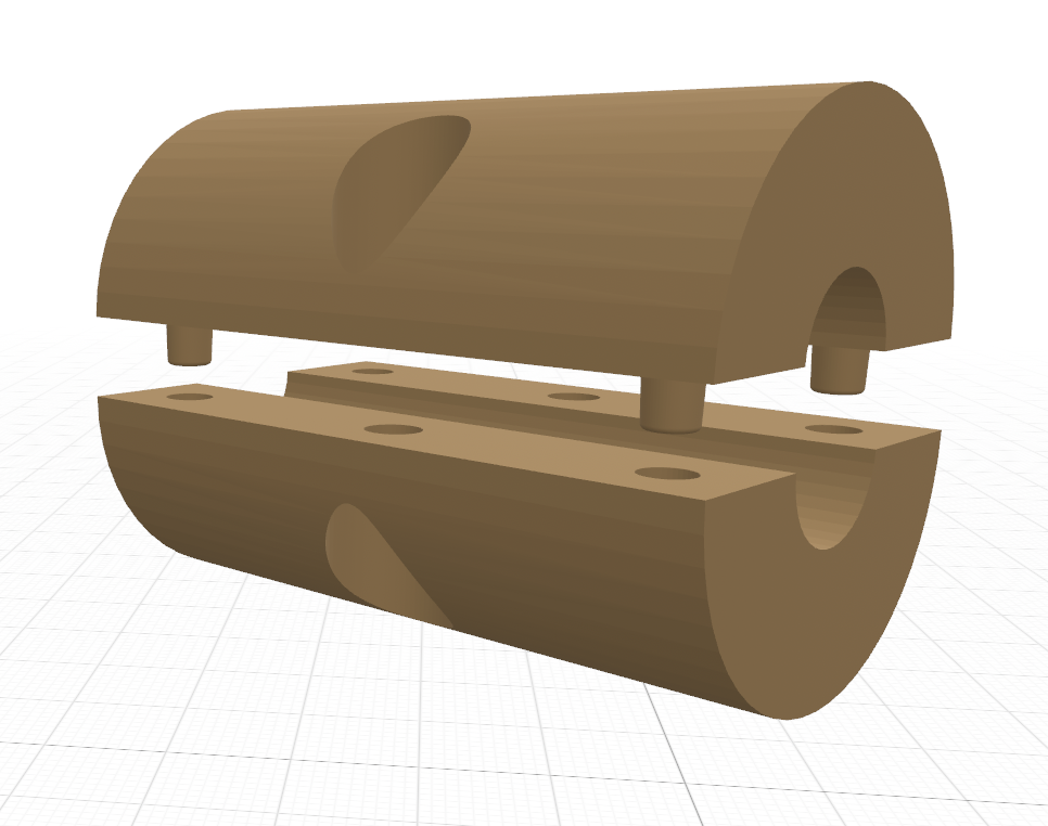
The cable trap contains two half-cylinders that act as a cylindrical capacitor. The capacitance (F/m) and inductance (H/m) of the cable trap can be computed using the equations:
where
Use copper tape to cover the top and bottom half circles. Do not put copper tape on the flat surfaces and do not connect the two sides together with tape.
The files in the Trap_Cylinder/ folder has the design in two formats, in OpenSCAD (size customizable) and as a SOLIDWORKS file. There are also .stl examples that you can 3D print.
Connect the two cylindrical halves together using a nylon nut and bolt. Metallic bolts may work for non-MRI applications, making sure the bolts are not shorting the copper tape.
2. End PCB
The end PCBs are for the ends of the half-cylinder. Each half of the copper tape is attached (possibly by solder) to each half of the PCB. A tuning capacitor connects the two traces.
The files in End_Board/ contains KiCAD 6 files for the board, but this can also be implemented using copper tape or scrap PCB.
3. Cable Trap Cover
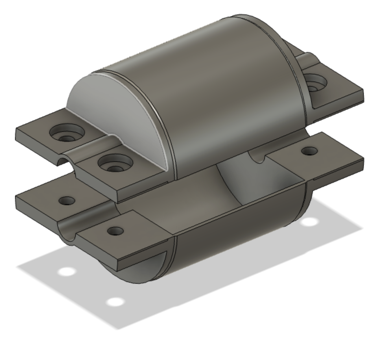
The optional cable trap cover provides protection and additional support to the cable traps. The files in Trap_Cover/ can be opened in Fusion360.
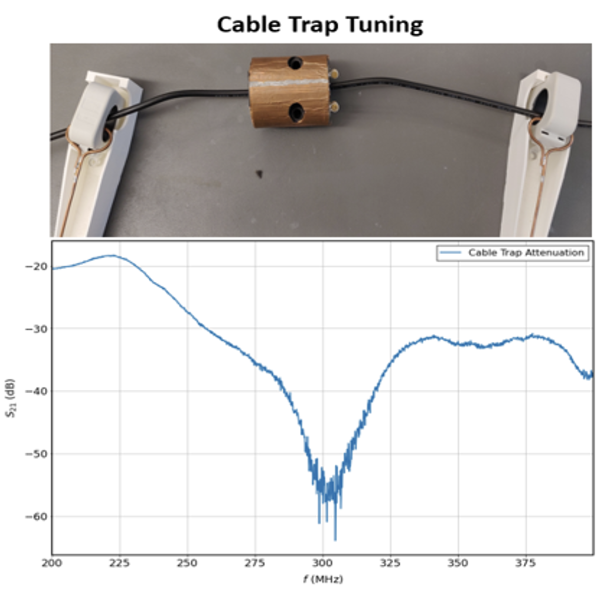
The cable trap can be tuned by placing a (50 Ohms) terminated coaxial cable, then measuring the current on both sides of the cable using an RF current probe connected to a network analyzer (S21). Adjust the tuning capacitor on the End PCB so that the minimum S21 is at the intended frequency.
Angel G Enriquez
Jana M Vincent
Folk W Narongrit
Thejas Vishnu Ramesh
Joseph V Rispoli*


