Lab(2): Interrupt handling with PIC Microcontroller
1. Introduction:
Digital interrupts represent one of the main concept used in modern computers and embedded systems. In this lab, we’ll explore close the usage of this concept in a real-life situation using one of the most common chips in Pic productions which is PIC16F877A.
2. Objectives
• Applying the concept of interrupts in HW project using PIC16F877A.
• Advancing the Simulation skills using Proteus as a simulator.
• Using PIC microC Pro as a compiler for C.
• Using MPLAB IPE as a compiler.
3. Requirements
- SW requirements:
• Proteus 8 Professional (or higher compatible versions)
• microC PRO for PIC v6.6 (or higher compatible versions)
• MPLAB IPE v3.50 (or any other burning software)
http://ww1.microchip.com/downloads/en/DeviceDoc/MPLABX-v3.50-windows-installer.exe
- HW requirements:
• PIC16F877A
• PICkit 3 Programmer (or any other working programmer)
• Crystal 4.000 MHz
• 12V DC Fan
• Relay 5V Coil
• 9V DC Battery
• UA741CN "General Purpose Single Operational Amplifier"
• Character LCD 2x16
• LM35dz "Temperature Sensor"
• L7805CV "Positive Voltage Regulator 5V"
• 1 kΩ - 10 kΩ resistor
Prerequisites:
• Basic understanding of C programming.
• Basic understanding of the Proteus schematic design.
• Basic knowledge of HW testing in debugging.
4. Procedure Review:
Interrupts are special events that requires immediate attention, it stops a microcontroller/microprocessor from the running task and to serve a special task known as Interrupt Service Routine (ISR) or Interrupt Handler.
Interrupt is the one of the most powerful features in embedded applications. Almost all the real-time applications are implemented using Interrupts.
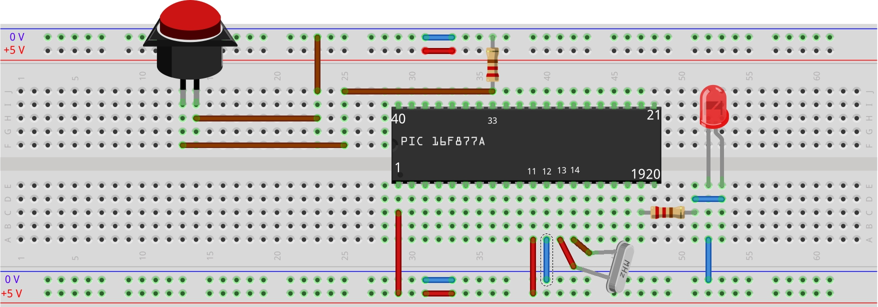
Before starting to explore the interrupts option in the (PIC16F877a) IC. A simple example should be implemented as a reminder on how to connect and use the IC.
Example 0:
Design a simple blinking led circuit that switches states between high and low every 1 second.
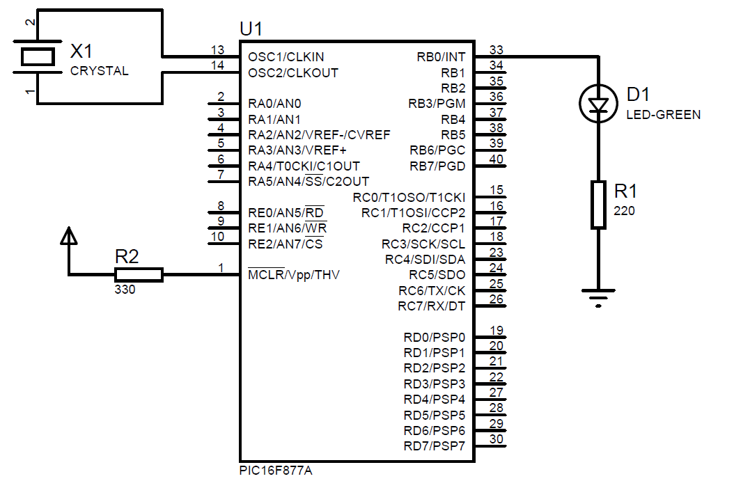
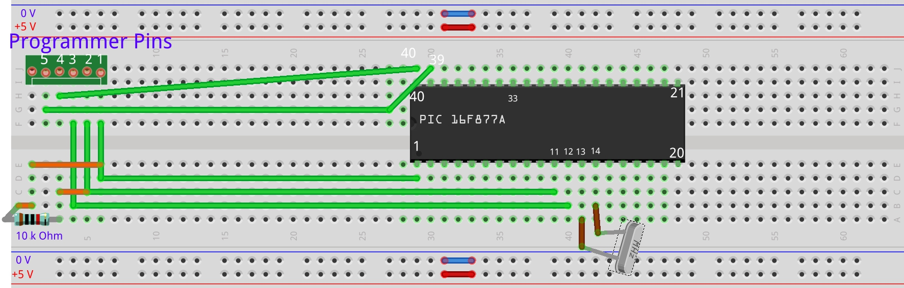
Board Connection:
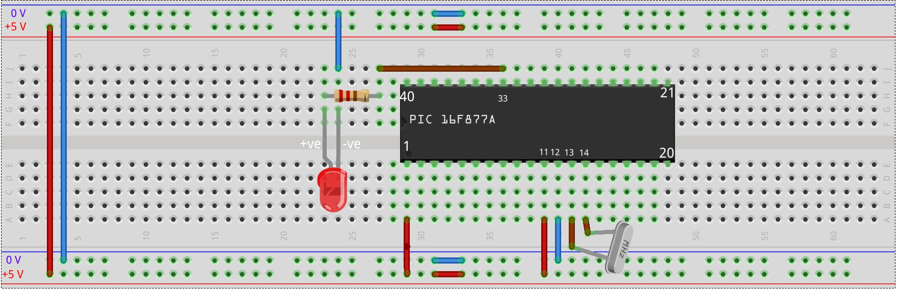
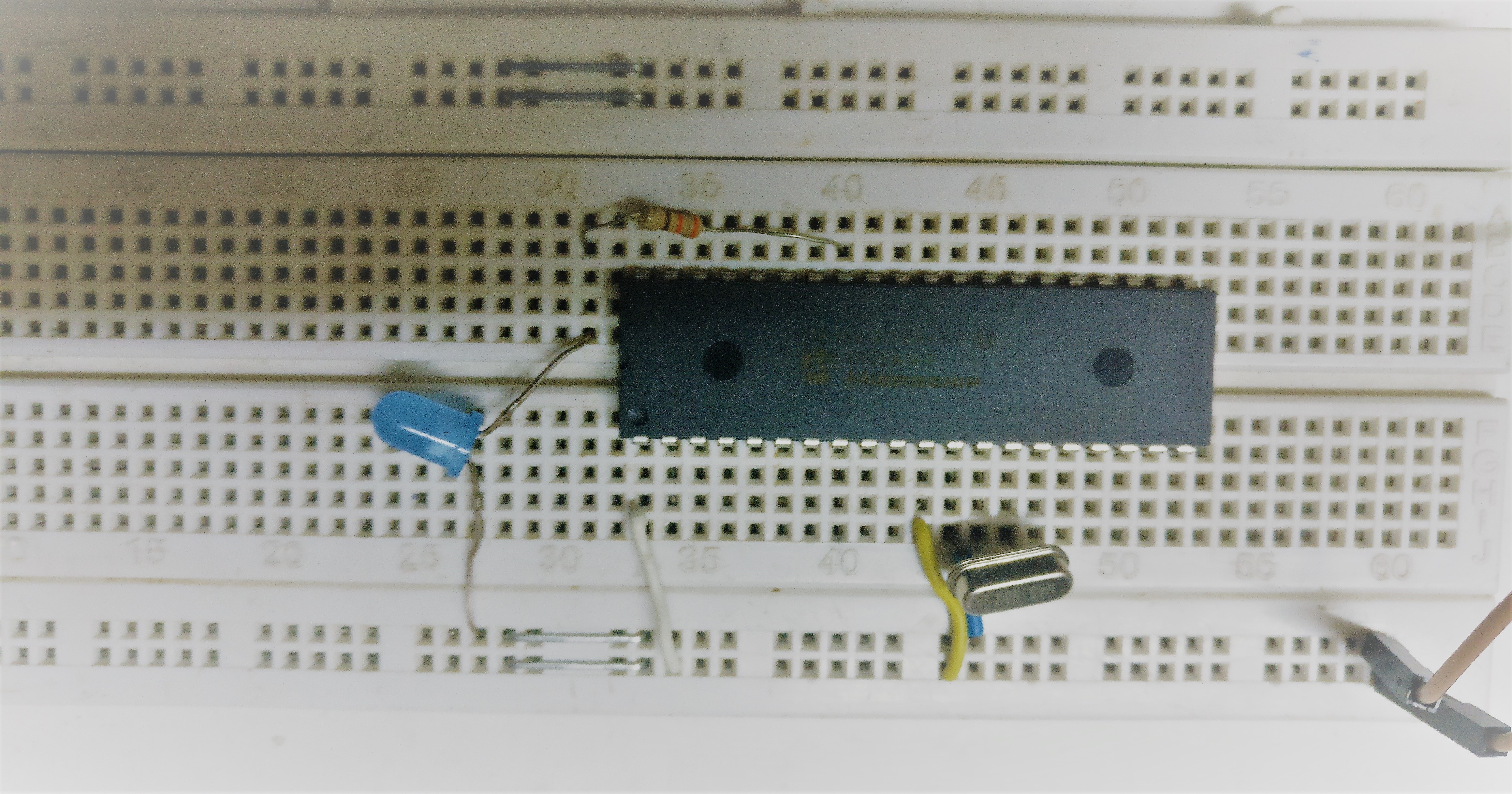
Real life view:
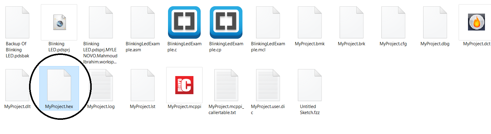
But how is the code burnt the PIC 16f8777a Chip? First write the blinking led code in your MicroC PRO for PIC and press compile as the following pic.
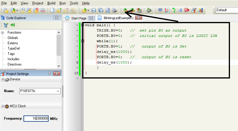
This will generate a hex file in your project path.
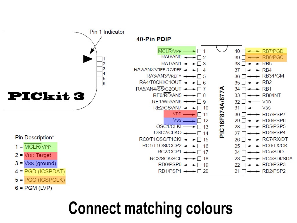
Then connect the PICkit 3 to the pic as the following figure suggests.
- Please remember to connect the Crystal to pins 13 and 14.
- Add a 10k resistor between PICkit 3 pins (1 and 2).
- Pin 6 is not connected.
- After you make sure that the connections are right. Connect the USB to your Desktop and the programmer.
-
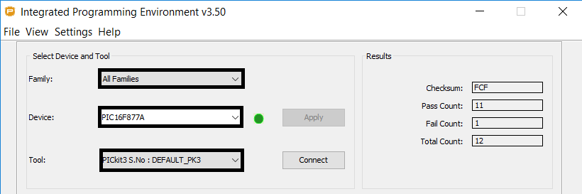
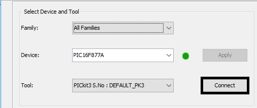
Open the MPLAB IPE v3.50 and Select the device and tool.
-
From Settings menu choose Advanced Mode.
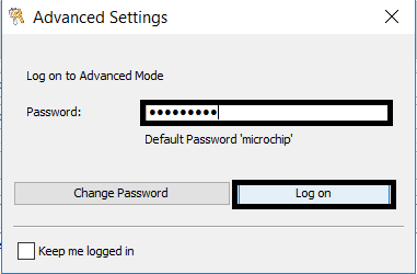
-
Type the default password is: microchip then login.
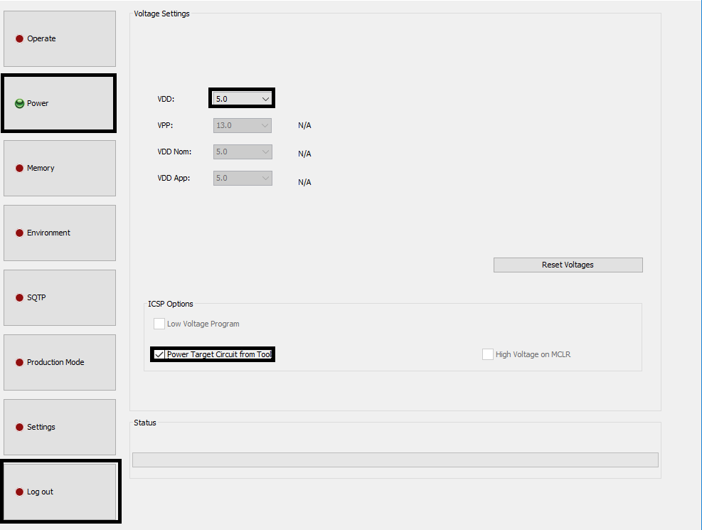
- Press the power button then choose VDD = 5 and mark the check box in the figure below then log out using the log out button on the left side.
- After making sure all the circuit and PICKit connections are right press connect.
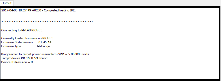
Press ok for this warning.
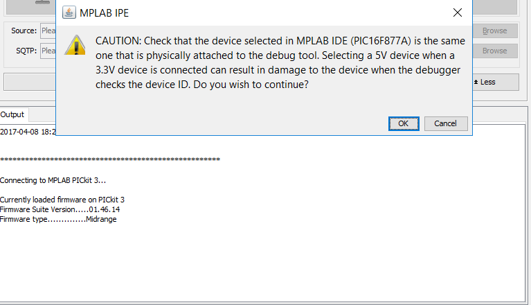
If the output displays: Target device PIC16F877A found. Then your connection is right.
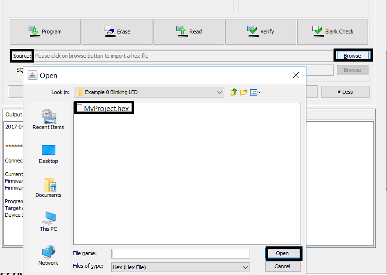
- To start programming (writing) the hex file to the Chip. Press source then navigate to the path of the hex file you’d like to burn and choose it.
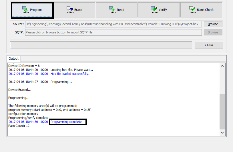
After that press program and wait until the programming is complete.
The previous steps could be repeated whenever required. In the following pages, we shall explore in some detail the interrupts available in the 16f877a chip and make use of them in a real-life scenario.
PIC 16F877A has the following 15 interrupt sources:
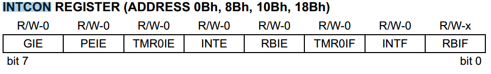
• External (Enabled by setting bit <4> bit in Register INTCON) which is named INTE. Occurs when on a rising edge (By default) on PORTB<pin 0>. It sets the INTF flag bit. INTF which is no 1 in register INTCON.
• Timer 0 (Enabled by setting bit TMR0IE no <5> in Register INTCON)
• RB Port Change (Enabled by setting bit <3> in Register INTCON) which is named RBIE. Occurs when an input changes on PORTB<pin 4 to 7>. It sets RBIF flag bit. RBIF which is no 0 in register INTCON.
• Timer 1 (Enabled by setting bit 0 in Register PIE1)
• Parallel Slave Port Read/Write (used when interfacing with another µp Enabled by setting bit <7> in Register PIE1)
• A/D Converter (Enabled by setting bit <6> in Register PIE1)
• USART Receive (Enabled by setting bit <5>) in Register PIE1)
• USART Transmit (Enabled <4> by setting bit in Register PIE1)
• Synchronous Serial Port (Enabled by setting bit <3> in Register PIE1)
• CCP1 (Capture, Compare, PWM) (Enabled by setting bit <2> in Register PIE1)
• CCP2 (Capture, Compare, PWM) (Enabled by setting bit <0> in Register PIE2)
• TMR2 to PR2 Match (Enabled by setting bit 2 named TMR2ON in Register T2CON)
• Comparator (Enabled by setting bit in Register)
• EEPROM Write Operation (Enabled by setting bit <3> in Register PIE2)
• Bus Collision (Enabled by setting bit <3> in Register PIE2)
In this Lab, the main focus would be on the 1st and the 2nd interrupt. The 3rd one , which is also in Bold, has similar working concept as the first one.
Here’s a Full view of how an interrupt occurs in a PIC16F877A IC:
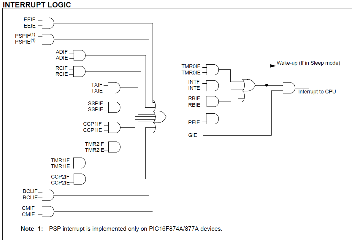
Lab 8 1st figure
Example 1: Implementing an external interrupt
Design a system that toggles a led based when an External Rising edge interrupt occurs. (Hint use External Interrupt)
 https://youtu.be/I50_92KFlvQ
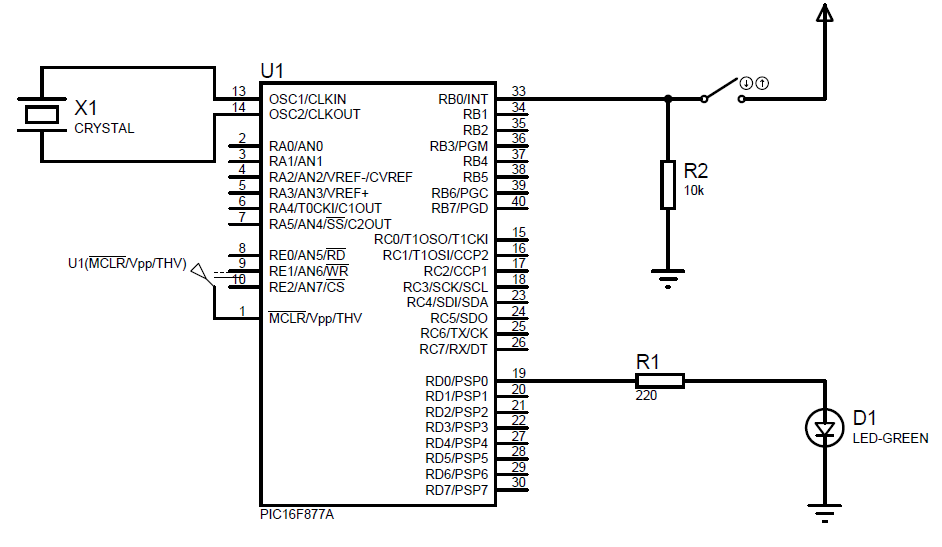 Lab 8 2nd figure
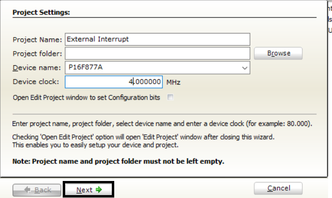
Open mikroC PRO and set the Project settings with appropriate values:
Lab 8 2nd figure
Open mikroC PRO and set the Project settings with appropriate values:
Continue with default settings. Write the following code:
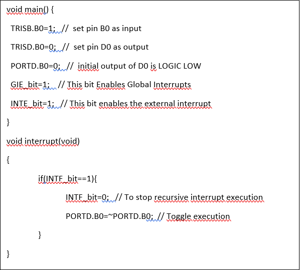
Let’s discuss the Execution of this code. The program starts Execution from the main function.
The first line is
TRISB.B0=1
It literally means tristate of pin B0 is enabled.
As know from logic the tristate (third state) is the Hi-Z state which is needed when the pin B0 works as an input to avoid the loading effect and read the input accurately.
TRISD.B0=0
This line means that Pin D0 doesn’t have a third state which means it can only be either high or low (output).
PORTD.B0=0
Initial output state of D0 is output LOW.
GIE_bit=1
This bit value in the INTCON register is responsible for enabling (when set with 1) or disabling (when reset) all the other interrupts (lab8 1st figure).
INTE_bit=1
This bit value is responsible for enabling external interrupts.
void interrupt(void)
The default interrupt handler and is executed whenever an interrupt occurs regardless of its type. That’s why we need an if statement to check for its type when there are multiple interrupts.
if(INTF_bit==1)
This checks if the flag INTF_bit is set (with 1) which means that an external interrupt at pin B0 has occurred ( in this case a rising edge).
INTF_bit=0
If we forget to write this line the interrupt function would keep executing indefinitely.
PORTD.B0=~PORTD
This line is to toggle the led (change the state of the led either on to off or off to on).
Example 2: Implementing a timer interrupt
Design a system that displays the number of seconds elapsed since it turns on using a 2*16 LCD screen. (Hint use a TMR0 interrupt).
First we need to understand How this kind of interrupt operates:
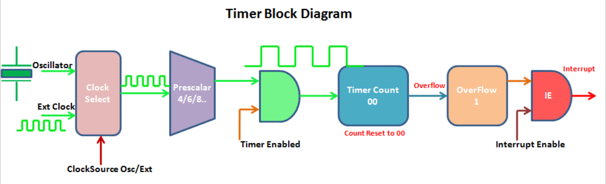
Lab 8 3rd figure source: exploreembedded.com
The main idea behind any timer is to wait for a number of ticks that the user needs in order to perform an action there’s a built-in oscillator which is T0 clock quarter the external oscillator frequency and (of course four times the time period), Which is a 4 MHZ/4 in this case.
The timer counts from a specific value decided by the user in the TMR0 (8-bit register) to 255 (FF) and the next tick makes an overflow where the interrupt occurs if the GIE is set (the General interrupt register is set to 1 which means that interrupts are activated.
Now all we need to know is how much time does a single tick take and then multiply it by the number of ticks from let’s assume 0 to 255.
Tic time = Number of available counts * oscillator time period
In our example the timer frequency is 1 MHZ so the timer OSCilator time period is 1 µs.
This is a very small value and we only have at max 256 tics to enable the interrupt.
We need to figure out a way to enlarge the tick time. Luckily for us it’s implemented in the PIC16F877A a Pre-scaler value which can increase the tic time which is either 1,2,4,8,16,16,32,64,128,256.
Now the tic time could be increased up to 256 Times. To sum up Interrupt occurrence delay can be calculated from the following equation:
Interrupt delay = Oscillator time periodnumber of ticsprescaler
And since the oscillator here is the external 4 MHZ crystal so the
Timer0 time period = 4 / FOSC
FOSC: frequency of external Crystal oscillator
number of tics = 256 – TMR0 stating value
prescaler value depends on the PSA0 PSA1 PSA2 values which is according to the datasheet

Bit Value: PS2 PS1 PS0 The general formula is
Timer interrupt delay Time =

Now. We want to determine a suitable value for interrupt execution (Assume 8 ms)
So, every 125 interrupts the clock should increment the second time by 1.
Assume a prescaler of (32) and the Crystal frequency is 4 MHZ. Now solve for TMR0 starting value which is 6 in this case.
Before the example code, first there are a few register bits we need to know how they work.
TMR0: counts from a specific value (determined by software or zero by default).
T0CS: when reset (Equals 0) the Internal instruction cycle clock where f = FOSC /4
PSA: when reset, the prescaler is assigned to the timer0 module.
PS2, PS1, PS0: (ddd) take values from binary (000) to binary (111) and determine the prescaler value.
Example 2: Implementing a timer interrupt
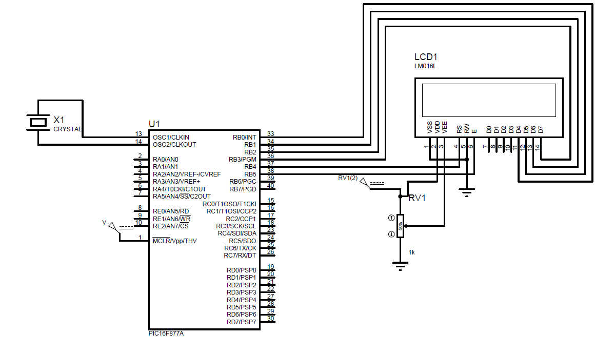
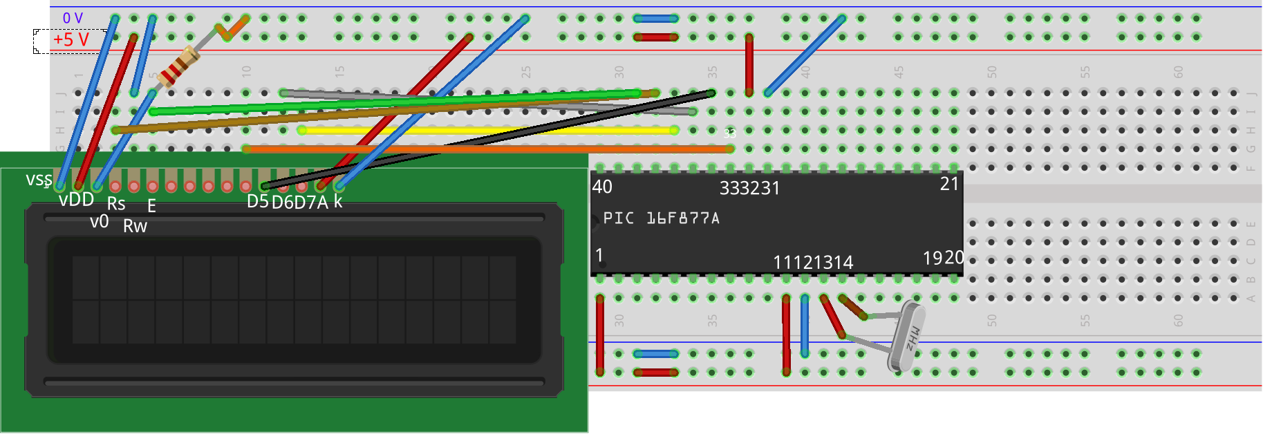
The schematic design is easy enough just a 2*16 LCD connected to the B pins (for further detail check the MicroC PRO Help menu )

5. Task1
-
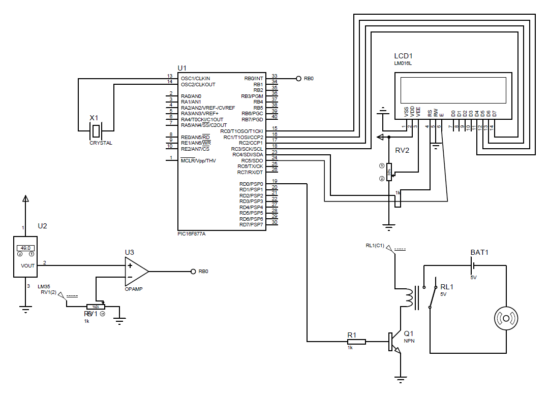
Apply the skills you gained in this Lab to make a system that uses the PIC16F877a. An interrupt is executed when the temperature reaches 50 degrees or higher. The ISR sends a signal that operates the fan and keeps working until the temperature is back below 50 degrees. Also, include a timer interrupt that is used to display the elapsed time since the last time the fan cooling system was operating. (Hint you can use the TMR0 interrupt with the INTE at pin B0 or RB interrupt at any pin in B4:7) The schematic should look something similar to this.
-
In case you have multiple interrupts explain the priority by which your interrupts are executed in the PIC16F877A.
Task2
Design a simple irrigation system that irrigates some plant every 3 days for 15 Secs. Use Timer interrupts to adjust the time.
Display on the 7-seg the total time spent since the last irrigation.
Task3
Design a model for a garage security system.
The garage motor runs for 4 seconds to open after the right password is entered.
Use timer interrupts to adjust the period.
6. Additional material
PIC16F877A datasheet:
microchip.com/downloads/en/DeviceDoc/39582b.pdf
Recommended readings:
Interrupts with PIC µc: electrosome.com/interrupt-pic-microcontroller
timer interrupt Calculate: microcontrollerboard.com/pic-timer0-tutorial.html