Maduino Zero Lorawan
/*
Version:		V1.3
Author:			Vincent
Create Date:	2021/5/19
Note:
		V2.0:Change for Ra08
		V1.3:Change Wiki Link
		V1.2:Add Maduino Zero Lorawan Change Frequence.docx
		V1.1:Add At command explain.
*/
[toc]
Makerfabs
Maduino Zero Lorawan
Intruduce
Product Link :Maduino Zero LoRaWAN
Wiki Link : Maduino Zero LoRaWAN Node
Maduino Zero LoRaWan is a solution based on ATSAMD21G18 MCU and LoRaWAN module Ra-08H. The LoRaWAN module Ra-08H is based on the ASR6501 chip, it integrated the LoRa radio transceiver, LoRa modem, and 32-bit RISC MCU, to support LoRa modulation mode and (G) FSK modulation mode. Maduino LoRaWan acts as a LoRaWAN node to transmit/receive the local data to the network by connecting LoRaWAN Gateway. With this module, users are easy to prototype LoRaWAN projects easily in few hours.
Feature
- ATSAMD21G18, 32-Bit ARM Cortex M0+
- Interface: I2C/SPI/UART/18*GPIO
- With super anti-interference ability, it can work normally in complex interference environment.
- Minimum receiving sensitivity: -137dBm (SF=12/BW=125KHz)
- Maximum transmit power +21dBm
- Working frequency: (Ra-07) 410mhz ~ 525mhz (default), (Ra-07h) 803mhz ~ 930mhz (default)
- Power supply voltage input: 3.3V
- Transmitting working current: 107mA (full load power consumption)
- Receive working current: 6mA
- Sleep current: 3uA
Front:
Back:
Example
V2.0 Change Frequence
The module supports 868MHz and 915MHz Lorawan communication, but requires upload different firmware.
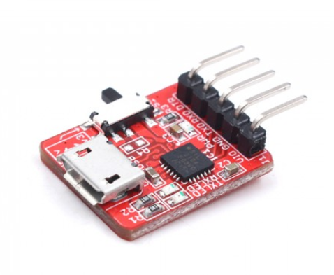
You must need Makerfabs Down tools or USB to TTL tools
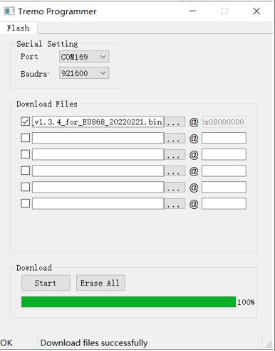
1, Open firmware_update_tool/ TremoProgrammer_v0.8.exe
2, Select firmware you need.
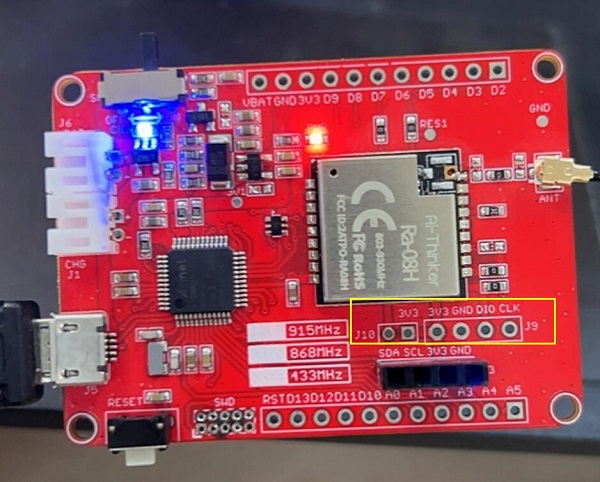
3, Connect MakerFabs CP2104 USB2UART to Maduino Zero Lorawan.
| USB2UART | Maduino Zero Lorawan |
|---|---|
| VCC | 3.3V |
| GND | GND |
| TX | CLK |
| RX | DIO |
4, Connect J10 and 3V3 with a wire
5, Click Download
6, Press RESET button on Maduino
7, Wait download over
Compiler Options
If you have any questions,such as how to install the development board, how to download the code, how to install the library. Please refer to :Makerfabs_FAQ
- Install library : DHT_sensor_library.
- Upload codes, select "Arduino Zero" and "Native USB"
Example List
at-test
Simple at command test demo
at-test-lorawan
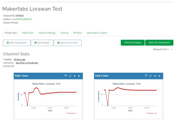
Register the Lorawan gateway in OTA mode and send data to the TTN. And send message to ThingSpeak.

test_SD
Simple SD card test for read and write.
downlink_control
Using TTN console send a download message to Maduino.
AT Command Explain
AT+CDEVEUI?
Inquire DEVEUI right now.
AT+CDEVEUI?
AT+CDEVEUI=<DevEUI>
Set DEVEUI, APPEUI and APPKEY.
AT+CDEVEUI=<DevEUI:length is 16> AT+CAPPEUI=<AppEUI:length is 16> AT+CAPPKEY=<AppKey:length is 32>
OTAA join mode need these three numbers.
AT+CJOINMODE=<MODE>
Set join mode via OTAA.
AT+CJOINMODE=<MODE> <MODE> 0:OTAA 1:ABP Defualt mode is OTAA.
AT+CJOINMODE=0
AT+CCLASS=<MODE>
Set lorwan mode.
AT+CJOINMODE=<MODE> <MODE> 0:ClassA 1:ClassB 2:ClassC
Defualt mode is ClassA.
AT+CCLASS=0
AT+CJOIN=<ParaValue1>,[ParaValue2],…[ParaValue4]
Join Lorawan to Lorawan webgate.
AT+CJOIN=<ParaValue1>,[ParaValue2],…[ParaValue4]
<ParaTag1>
0: Stop JOIN 1: Start JOIN
[ParaValue2]
0: Disable Auto JOIN 1: Enable Auto JOIN
[ParaValue3]
JOIN cycle,range 7 to 255, unit is second。 Default value is 8.
[ParaValue4]
Maximum number of access attempts,range 1 to 256.
AT+CJOIN=1,0,10,1 Set JOIN parameter: Start join, disable automatic join, try period is 10s, maximum attempt times is 8.
AT+DTRX=[confirm],[nbtrials],<Length>,<Payload>
Send one message to webgate,and receive message.
AT+DTRX=[confirm],[nbtrials],<Length>,<Payload>
[confirm]
0: UnConfirmed up message
1: Confirmed up message
[nbtrials]
Set sending times. Confirm and nbtrials refer to the corresponding AT instruction, valid for this dispatch only, optional.
<Length>
Represents the number of strings. The maximum value is specified in the access specification. The length of bytes allowed to be transmitted is different at different rates (see the Lorawan protocol for details). 0 indicates that empty packets are sent.
<Payload>
Hexadecimal (2 characters for 1 number)
AT+DTRX=1,2,5,0123456789
OK+SEND:05
OK+SENT:01
OK+RECV:02,01,00
Confirm data sent successfully, valid data received by server should be 0x01 0x23 0x45 0x67 0x89. And received downlink confirmation 0x02,0x01,0x00.


