- Script based on the fantastic tutorial "ESP32-CAM Take Photo and Save to MicroSD Card" written by Rui Santos at Random Nerd Tutorials
- Original tutorial in: https://randomnerdtutorials.com/esp32-cam-take-photo-save-microsd-card/
- The original sketch, written by Rui Santos, the ESP32-CAM takes a picture and then enters in sleep mode.
- The sketch here implements a slight modification. Now, the ESP32-CAM doesn't goes to the sleep mode after taking a picture.
- It takes a picture every 60 seconds and saves it in the MicroSD card attached to the ESP32-CAM.
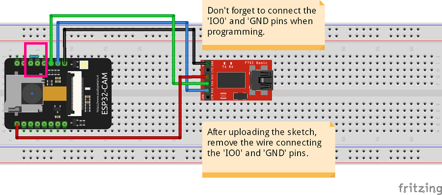
- The diagram above uses an FT232R programmer to upload the sketch to the ESP32-CAM.
- Connections:
IO0(ESP32-CAM) -GND(ESP32-CAM)GND(FT232R programmer) -GNDpin (ESP32-CAM)VCC(FT232R programmer) -5Vpin (ESP32-CAM)TX(FT232R programmer) -U0Rpin (ESP32-CAM)RX(FT232R programmer) -U0Tpin (ESP32-CAM)
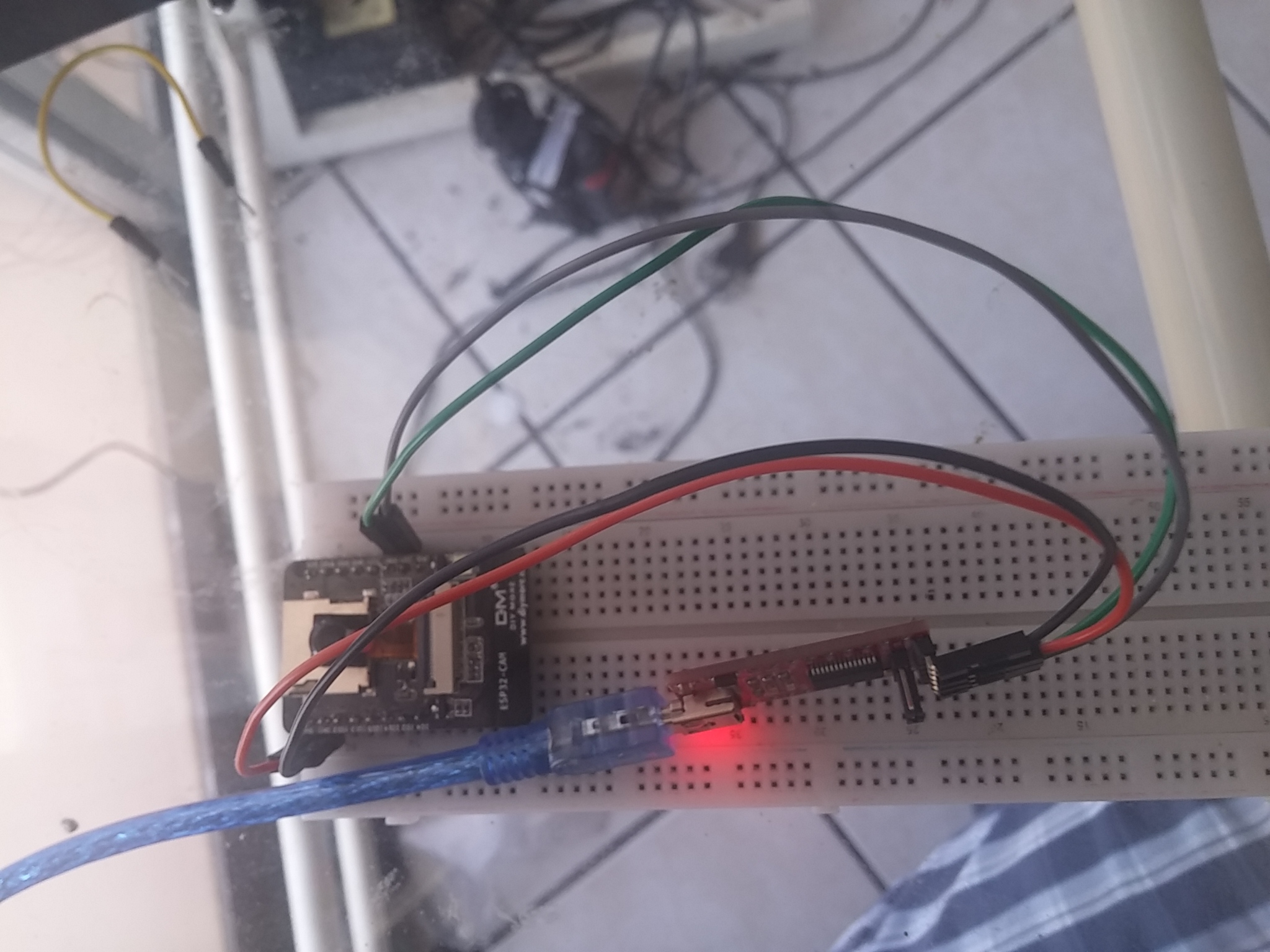
- The picture above shows the ESP32-CAM in programming mode, using a FT232R programmer module.
- Don't forget to connect the
IO0andGNDpins of the ESP32-CAM (yellow wire in the picture abore).
- After uploading the sketch to the ESP32-CAM, disconnect it from the PC and remove the yellow wire.
- Then, connect it again to the PC (or in power) and then it will work!
- It will take a picture every 60 seconds and save then in the attached MicroSD card.

