This manual is made for an IoT school project. I've created an IoT fan called WiFan. You can control the fan using an app, a voice assistant, or you can connect it to a weather API to turn on when the temperature rises. In this manual I will show you how I connected my fan to an open weather API using a NodeMCU ESP8266.
The manual will be divided into 5 steps:
- 🕹️ Connecting the Relay to the Microcontroller
- 🔌 Connecting a power cable to the Relay
- 🌦️ Setting up the Weather API
- ⌨️ Creating the code for the Microcontroller
- 🤯 Putting everything together to make a working product
When following this manual, I assume that you have the following hardware & software installed. If this is not the case, please set-up your Microcontroller correctly before following this manual.
- NodeMCU ESP8266 Microcontroller (or similar board)
- Relay Module
- Extension Cord (optional but preferable)
- Fan
- Arduino IDE
- NodeMCU USB Drivers
- ArduinoJson
- WiFiClientSecure
- ESP8266WiFi
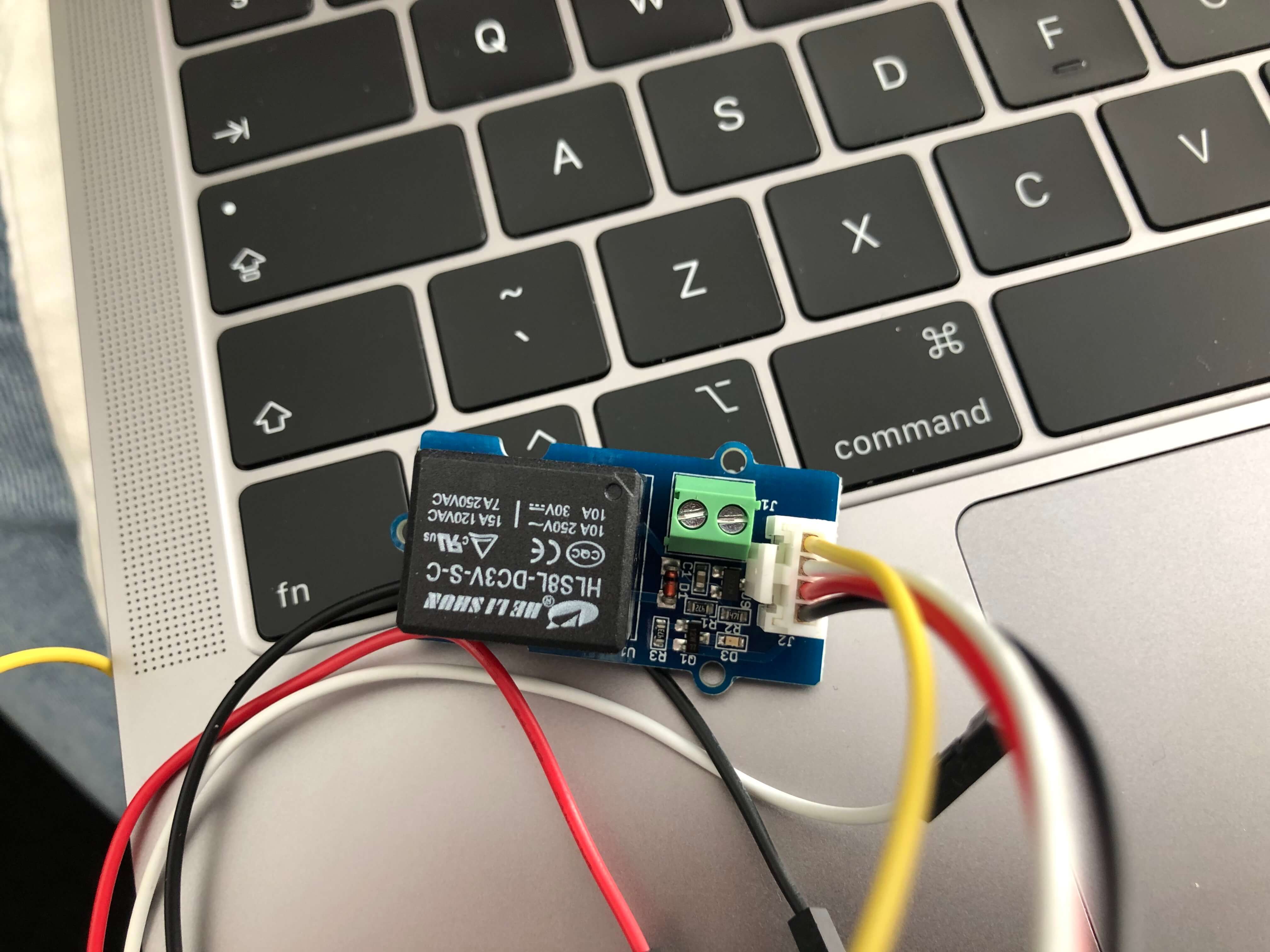
Connect your Microcontroller to your computer via USB. Then take your relay and connect it to your Microcontroller. My relay looked something like this:
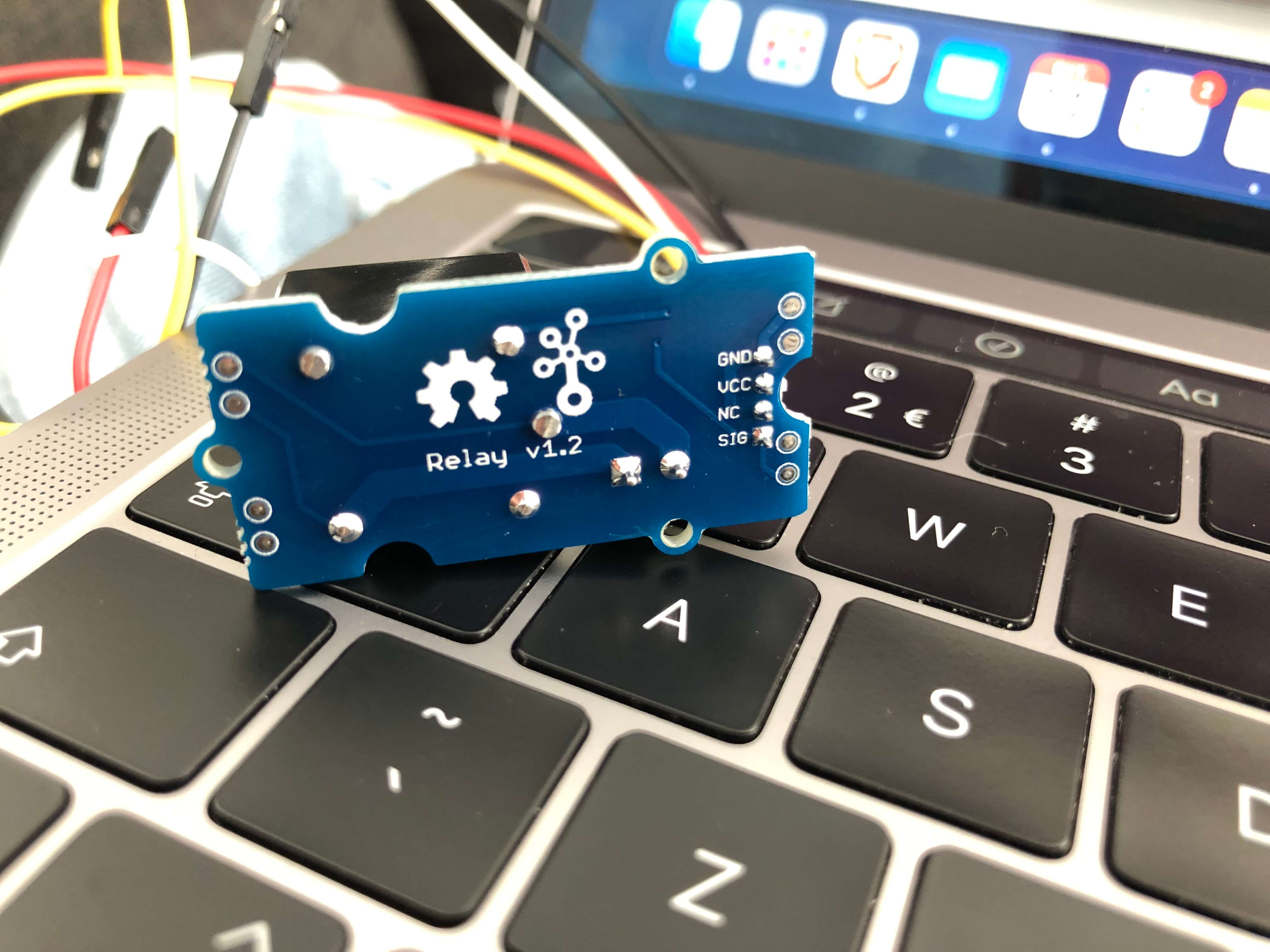
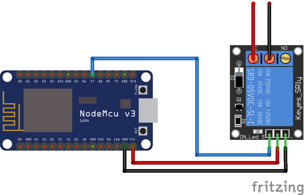
As you can see my relay has 4 pins: GND, VCC, NC and SIG. For this case, I'm only using GND, VCC and SIG. The white cable (NC) remains unplugged. I found this awesome guide on connecting a relay to a Microcontroller. The guide includes the following illustration, showing you how to connect every wire:
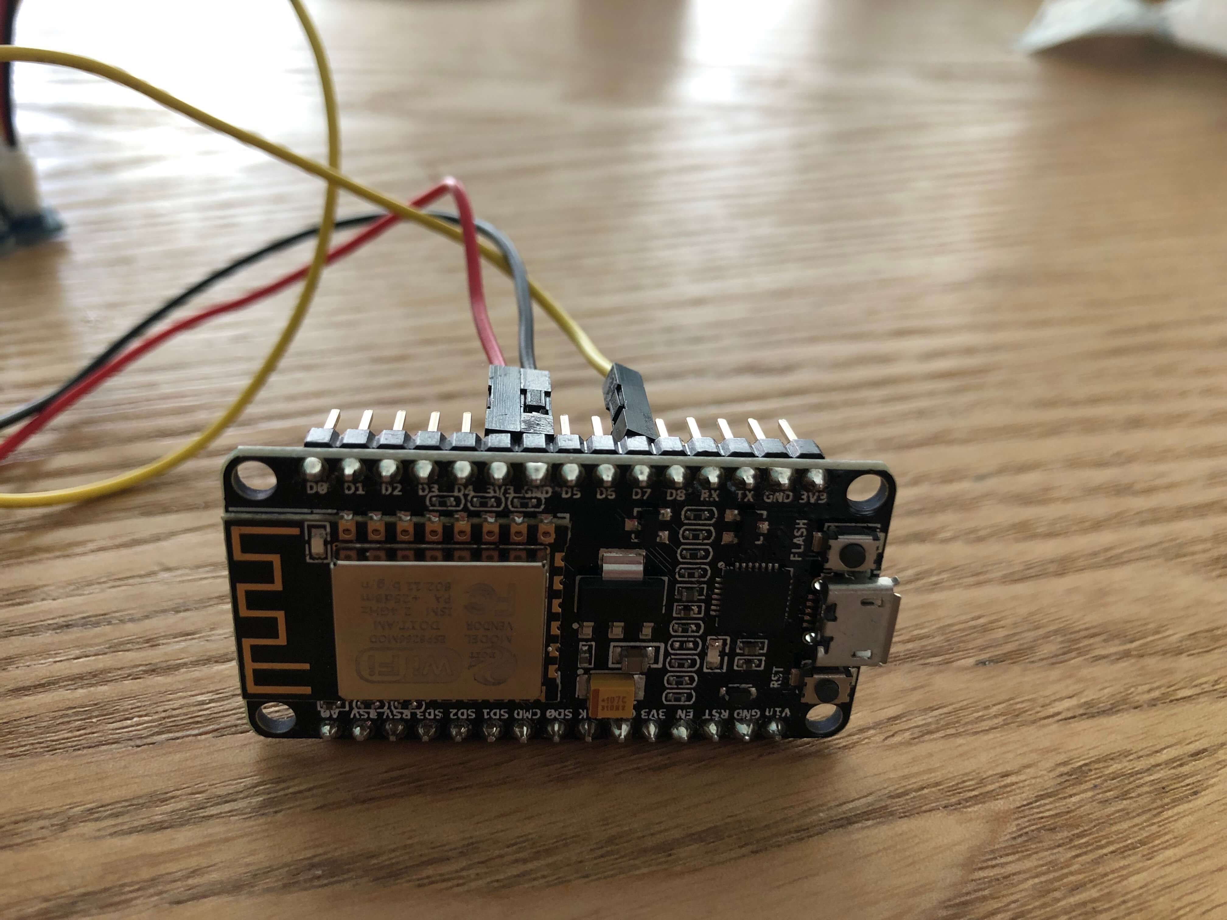
Connect the black wire (GND) with the Ground pin on your ESP8266 and connect the red wire (VCC) with the 3V3 pin on your board. Leave the white wire unplugged and connect the yellow wire (SIG) with the D7 pin on your board.
Warning! Connect these wires carefully. The guide I used, and the picture above told me to connect the VCC on the relay with the VIN pin on your board when using an ESP8266 or ESP32, because you need a 5V output. I’ve tried it, and my wire immediately started smoking, so please don’t make the same mistake. The 3V3 pin works fine for me instead.
With everything connected, your board should look something like this:
After connecting the wires, it is time to test our relay. I used the following code:
int relay = D7;

void setup() {
  pinMode(relay, OUTPUT);
}

void loop() {
  digitalWrite(relay, HIGH);
  delay(2000);
  digitalWrite(relay, LOW);
  delay(2000);
}
This simple program starts by turning on the relay. 2 seconds after that, it turns off. 2 seconds later, the loop function starts again. This is a simple way to test if everything is working so far.
Did everything work as planned? Congrats! 🥳. Let's move onto the next step.
A relay is a low-power electrical switch which toggles on and off a high-power (Max 250V) circuit. For this reason, we need to connect the relay to the power cable of the object we want to switch on and off. In this case it's a fan. Because I didn't want to ruin my fans power cable, and I might want to use different devices in the future, I decided to use an old extension cord. If you're like me and you don't have experience cutting and stripping wires, I recommend using an extension cord with a switch. With this extension cord, you can just remove the switch to reveal the wires.
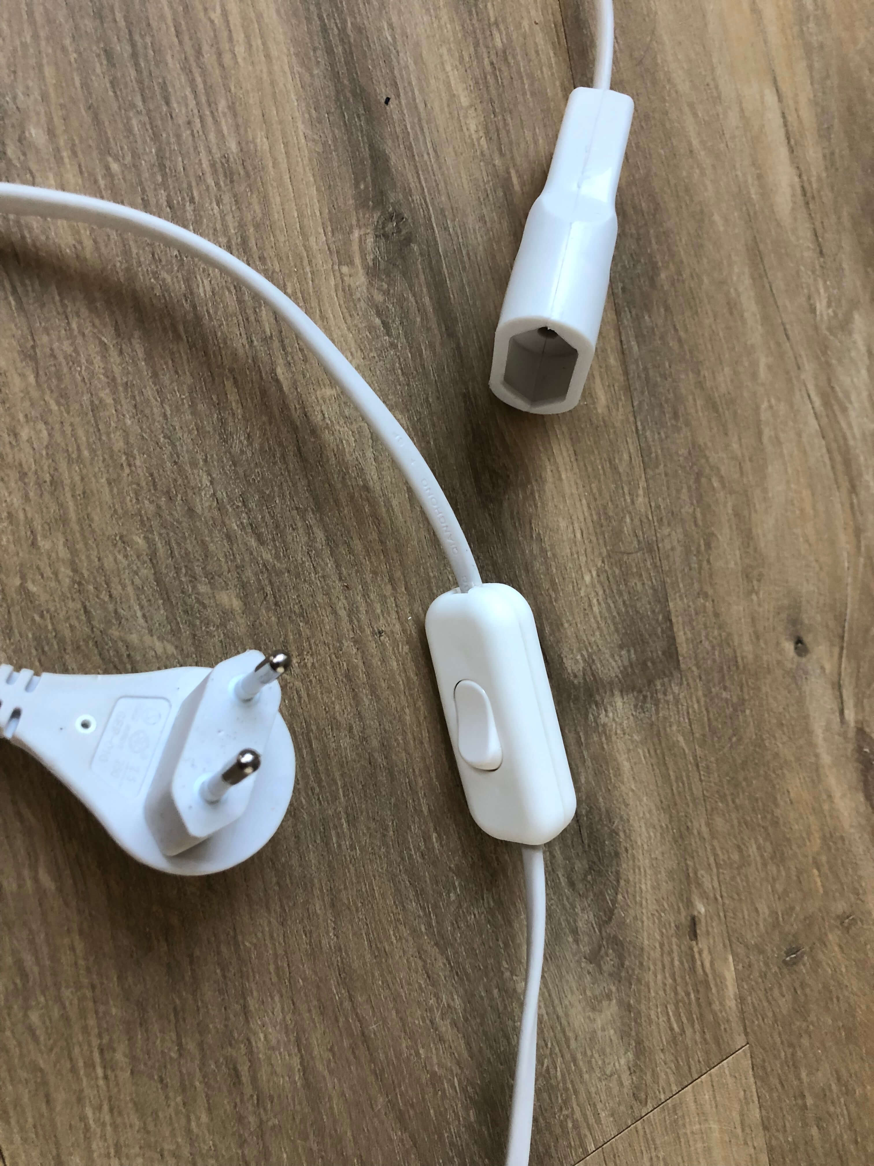
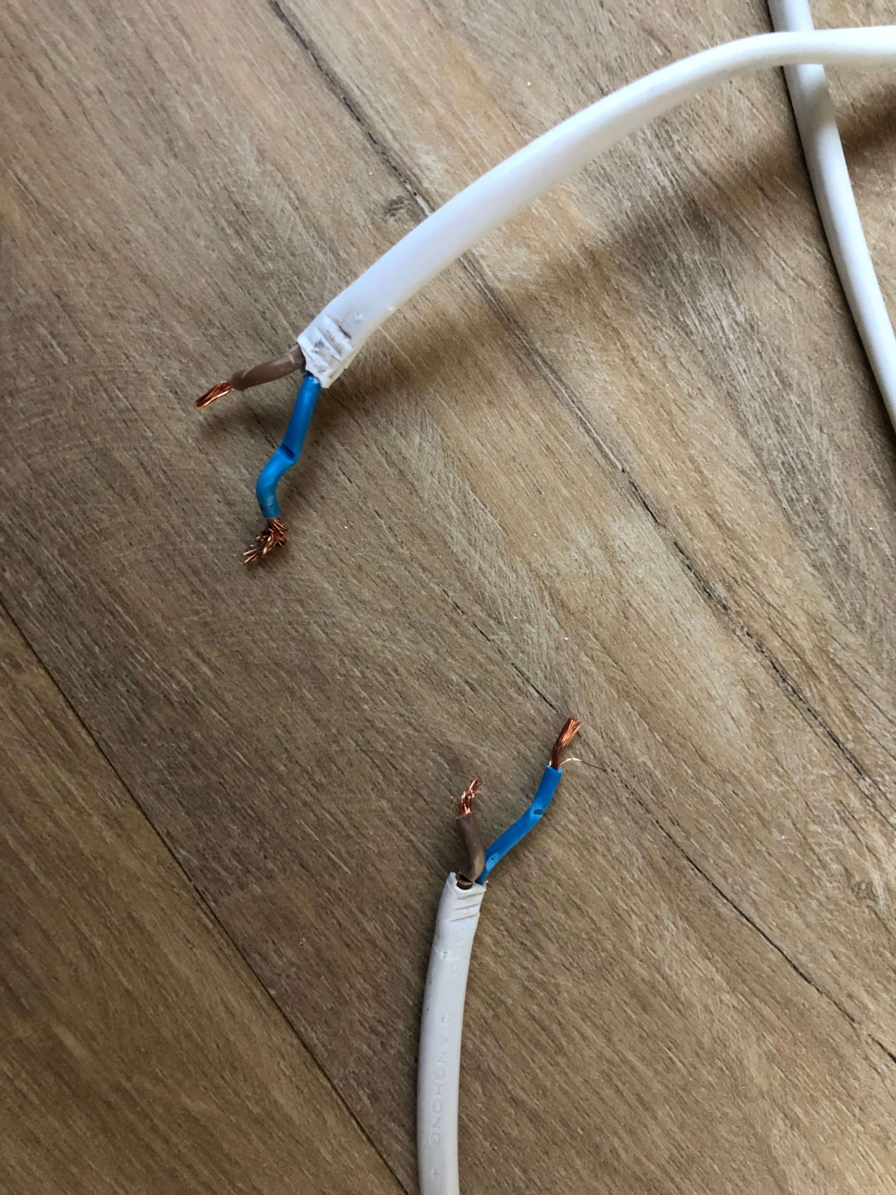
My extension cord looked something like this. As you can see it has a switch, which makes it easy for me to connect the relay. You do need to use a terminal block however with this cord, because both wires will be exposed when you remove the switch, and you only need 1 for the relay. After removing the switch or cutting open the cable and revealing/stripping the wires, your extension cord should look something like this:
As you can see in the picture my extension cord is an ungrounded cable. This might make it a bit easier to connect, but you can't connect every device to this extension cord, because most bigger devices have grounded plugs. I found this out too late which prevented me from connecting the fan I wanted to connect.
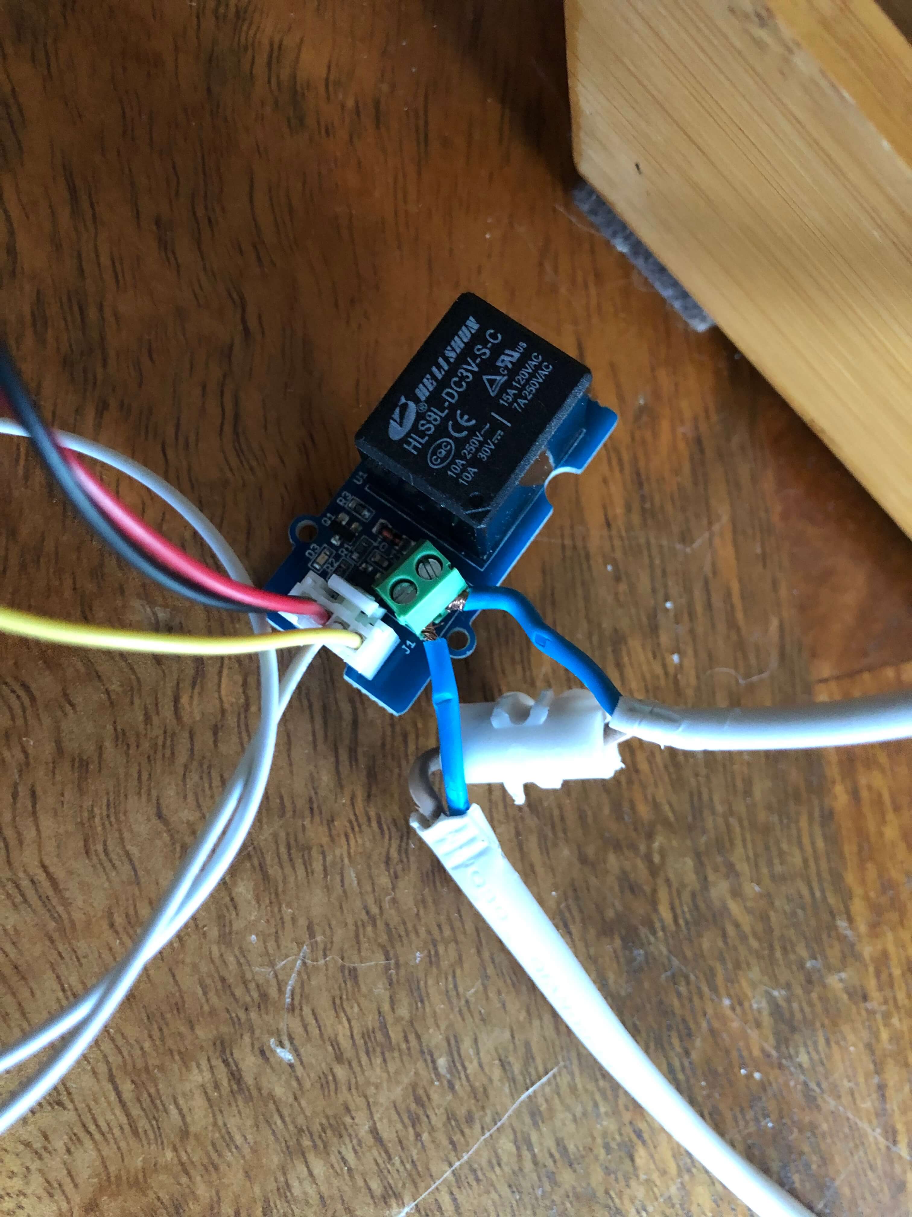
Now you can connect your relay to one of the two cables. Just put both stripped ends of 1 wire in your relay and screw it down. Put a terminal block on the other cable to continue the circuit. After you've finished connecting the relay, it should look something like this:
You can see I've connected the blue cable to the relay and the brown cable to the terminal block.
Now it's time to test our Frankensteined extension cord switch. I used the same code as in step 1 to test the relay. I connected a lamp to the extension cord to see if it really works. The lamp should turn on and off every 2 seconds. I've made a video while testing it so you can see how it should work:
IMG_4137.mov
If everything worked as planned, we can move onto the next step 🥳
Now that we can control our fan using the Microcontroller, we want it to turn on/off based on our outside temperature. We can get this data from an open weather API. I used https://openweathermap.org/api. This API has a free plan, but you must make an account first. Click the link and follow the instructions below.
Click the orange _Subscribe_ button bellow Current Weather Data. You'll be sent to the next page with a list of free and paid plans. Click _Get API key_ on the free plan. Sign up by filling in your details, follow the instructions and confirm your account. After completing your account setup, you can get your private API key. While being logged in, click on your account name in the top right corner of the website. Then click on _my API keys_. On this page you can view your API keys. 1 Default API key is generated. Copy this API key and save it for yourself.To test if your API key is working, you can copy this URL and paste it in your browser. Replace 'city name' with your location and 'API key' with the API key you just generated.
api.openweathermap.org/data/2.5/weather?q={city name}&appid={API key}
You should see something like this:
I received an error the first time trying this. This was due to the API key needing a few hours to be activated. If you get an error as well, try again after a few hours or visit the Frequently Asked Questions
If you see JSON code, your API request worked. The only problem is the temperatures are not in degrees Celsius. To change this, add &units=metric after your URL. Your final code will then look like this:
api.openweathermap.org/data/2.5/weather?q={city name}&appid={API key}&units=metric
Receiving JSON code with temperatures in Celsius? Great! we can move onto the next step 🥳
And now for the fun part, but also the hardest part (for me at least), the code. This part took by far the most time, but I will keep it simple in this manual. I will post the full code below. You can copy everything, just change these 3 things:
char ssid[] = "???"; // REPLACE with your network SSID (name)char password[] = "???"; // REPLACE with your network keyclient.print("/data/2.5/weather?q=Amsterdam&appid=*****APIKEYHERE*****&units=metric") // REPLACE LOCATION AND APIKEY
#include <ESP8266WiFi.h>
#include <WiFiClientSecure.h>
#include <ArduinoJson.h>

char ssid[] = "???";       // REPLACE with your network SSID (name)
char password[] = "???";  // REPLACE with your network key
int relay = D7;

// For HTTPS requests
WiFiClientSecure client;


// Just the base of the URL you want to connect to
#define HOST "api.openweathermap.org"

void setup() {
  //Relay setup
  pinMode(relay, OUTPUT);

  Serial.begin(115200);

  // Connect to the WiFI
  WiFi.mode(WIFI_STA);
  WiFi.disconnect();
  delay(100);

  // Attempt to connect to Wifi network:
  Serial.print("Connecting Wifi: ");
  Serial.println(ssid);
  WiFi.begin(ssid, password);
  while (WiFi.status() != WL_CONNECTED) {
    Serial.print(".");
    delay(500);
  }
  Serial.println("");
  Serial.println("WiFi connected");
  Serial.println("IP address: ");
  IPAddress ip = WiFi.localIP();
  Serial.println(ip);

  // If you don't need to check the fingerprint
   client.setInsecure();
}

void makeHTTPRequest() {

  // Opening connection to server (Use 80 as port if HTTP)
  if (!client.connect(HOST, 443))
  {
    Serial.println(F("Connection failed"));
    return;
  }

  // give the esp a breather
  yield();

  // Send HTTP request
  client.print(F("GET "));
  // This is the second half of a request (everything that comes after the base URL)
  // REPLACE LOCATION AND APIKEY WITH YOUR OWN
  client.print("/data/2.5/weather?q=Amsterdam&appid=*****APIKEYHERE*****&units=metric"); // %2C == ,
  client.println(F(" HTTP/1.1"));

  //Headers
  client.print(F("Host: "));
  client.println(HOST);

  client.println(F("Cache-Control: no-cache"));

  if (client.println() == 0)
  {
    Serial.println(F("Failed to send request"));
    return;
  }
  // Check HTTP status
  char status[32] = {0};
  client.readBytesUntil('\r', status, sizeof(status));
  if (strcmp(status, "HTTP/1.1 200 OK") != 0)
  {
    Serial.print(F("Unexpected response: "));
    Serial.println(status);
    return;
  }

  // Skip HTTP headers
  char endOfHeaders[] = "\r\n\r\n";
  if (!client.find(endOfHeaders))
  {
    Serial.println(F("Invalid response"));
    return;
  }

  //Use the ArduinoJson Assistant to calculate this:

  //StaticJsonDocument<192> doc;
  DynamicJsonDocument doc(1024); //For ESP32/ESP8266 you'll mainly use dynamic.

  DeserializationError error = deserializeJson(doc, client);

  if (!error) {
    float temp = doc["main"]["temp"];
    String location = doc["name"];

    Serial.print("Temperature in ");
    Serial.print(location);
    Serial.print(": ");
    Serial.println(temp);

    if (temp < 25) {
      digitalWrite(relay, LOW);
      Serial.println("Fan turned off");
  } else {
      digitalWrite(relay, HIGH);
      Serial.println("Fan turned on");
  }


  } else {
    Serial.print(F("deserializeJson() failed: "));
    Serial.println(error.f_str());
    return;
  }
}

void loop() {
  makeHTTPRequest();
  delay(50000);
}
Getting this final code was a pain in the ass. Almost all manuals online are outdated and are using an old version of ArduinoJson or other obsolete pieces of code. This is just a few of many error messages I got.
After hours of trying, I finally found a recent and up to date source. This GitHub Repo saved this project and it is the base of my code. It didn't work immediately, however. The ESP board connected to my network, but it didn't get the API's data. The error message I received was the following:
It seemed to be a memory issue. I followed a tutorial that told me to calculate how much memory I need for my API and to change it in the code. The tool to calculate how much memory to use is called ArduinoJson Assistant. My result was the following:
It recommended 1024, so I changed my code from 192 to 1024
After changing this, the output in the serial monitor was as followed:
I couldn't be happier, it finally worked! 🥳
Now that I've got the API working, I can combine Step 1 (the relay code) with the rest of the code.
I've added these lines in my final code:
int relay = D7; & pinMode(relay, OUTPUT);
And I created the follow function to turn on the fan if the temperature is below 25 degrees Celsius:
if (temp < 25) {
      digitalWrite(relay, LOW);
      Serial.println("Fan turned off");
} else {
      digitalWrite(relay, HIGH);
      Serial.println("Fan turned on");
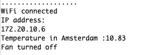
The result was this:
It worked!
I then added the current location for the temperature in the Serial Monitor. This made it easier to understand if it's working based on your location.
float temp = doc["main"]["temp"];
String location = doc["name"];

Serial.print("Temperature in ");
Serial.print(location);
Serial.print(": ");
Serial.println(temp);
The result was this:
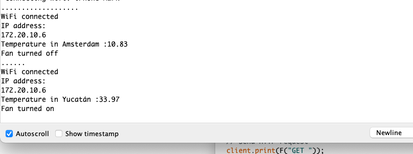
Awesome, everything works! 🥳 Just to proof everything is working, I changed my location to warmer place, in this case Yucatan. The serial monitor should print out a higher temperature and the fan should turn on. Fortunately, this was the case:
This is where I'm going to end this project. I did want to add some additional things, but this project was way harder than expected and it took me a lot of time. So, feel free to expand this project yourself with cool features!
