Tetroplater 
An open-source circuit for microwire tetrode gold plating, designed by Jumpei Matsumoto (Nishijo lab, Univ of Toyama).
Overview
See Nguyen et al., 2009 for the basics about tetrode gold plating.
Gold plating is necessary/effective for microwire tetrodes for recording neuronal activity. For the gold plating, the electrode tip is electroplated with current pulses, until the impedance reaches to the target value (see Fig 1B in Nguyen et al., 2009 for an example). The Tetroplater is an open-source low-cost (<200 dollars) circuit including an impedance meter and a current generator for tetrode gold plating.


Assembled circuit (left) and an example of a setup (right).
How it works
The Tetroplater measures the electrode impedance with a “auto-balancing bridge” circuit:

Here, the 1 kHz sin-wave oscillator signal (Vin = 3~4 mVp-p) is input to the electrode. The operational amplifier makes the voltage at the open circle zero. So, currents passing the electrode (Ielectrode) and Reference resistor Rref (Iref) become equal. Therefore, from Ohm’s row,
Relectrode / Vin = Rref / Vout
Where Relectrode is the impedance of electrode and Vout is voltages around Rref. Thus, by comparing the amplitudes of Vin and Vout, the impedance can be estimated.
The Tetroplater also has a 2.5-µA constant DC current source for electroplating.
Fabricating the circuit board
- Print the PCB from the eagle file (tetroplater.brd) or the gerber file (gerber_seeed_studio.zip; prepared for Seeed Studio).
- Get the electric parts in the list (digikey_cart.csv; the file can be import in DigiKey as a shopping cart. The quantities include spares).
- Assemble them according to the figure below.

Setting up with peripherals
- Connect ± 9~12 V power supply to V+, V-, and GND terminals.
- Connect the probes for the bath of gold plating solution and the electrode to BATH and EL terminals, respectively. Use the shield cables between the probes and the terminals and connect the shields to SHIELD terminal.
- Connect the V_MEA_IN, V_MEA_OUT and GND terminals to an oscilloscope.
- The rest of GND terminals can be used for electric shields around the electrode to reduce hum noise.
- Adjust oscillator amplitude (V_MEA_IN) to be 30~40 mVp-p by turning the trimmer potentiometer (R12).
.jpg)
An example of a setup. 1, the Tetroplater board; 2, a dual power supply; 3, an electrode holder (connected to the GND terminal); 4, a gold plating solution bath; 5, a metal plate (connected to the GND terminal); 6, a set of resistors for calibration; 7, an oscilloscope.
Usage
- Connect the probes to gold plating solution and an electrode wire.
- V_MEA_IN and V_MEA_OUT, shown in the oscilloscope, are 10 times amplified Vin and Vout, respectively.
- Push the switch on the board briefly. During the switch is on, 2.5 µA current passes for plating. Repeat it until the impedance (= 1 MΩ * V_MEA_IN / V_MEA_OUT) reaches the target range (see the video below). The target range can also be checked directly by measuring impedance of resistors of the corresponding values.
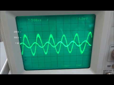
Because only Vout changes through the plating, oscilloscope with only one input channel also works (there is a cheap one)
Typical results
| Before (MΩ) | After (kΩ) | |
|---|---|---|
| Tetrode 1, ch 1 | 4.0 | 310 |
| Tetrode 1, ch 2 | 2.9 | 330 |
| Tetrode 1, ch 3 | 2.9 | 330 |
| Tetrode 1, ch 4 | 2.8 | 340 |
| Tetrode 2, ch 1 | 4.8 | 330 |
| Tetrode 2, ch 2 | 3.5 | 320 |
| Tetrode 2, ch 3 | 3.0 | 340 |
| Tetrode 2, ch 4 | 2.4 | 320 |
| Tetrode 3, ch 1 | 3.5 | 310 |
| Tetrode 3, ch 2 | 3.8 | 320 |
| Tetrode 3, ch 3 | 2.9 | 320 |
| Tetrode 3, ch 4 | 4.0 | 310 |
| Tetrode 4, ch 1 | 3.7 | 290 |
| Tetrode 4, ch 2 | 5.7 | 320 |
| Tetrode 4, ch 3 | 4.3 | 300 |
| Tetrode 4, ch 4 | 3.1 | 300 |
Impedances of four nichrome wire tetrodes (Sandvik Precision Fine Tetrode Wire) measured before and after gold plating with the Tetroplater (using Neuralynx Gold Plating Solution). The impedance values were checked with Thomas Recording Impedance Tester.

Signals from tetrodes gold plated with the Tetroplater (in neocortex, high-pass filtered)
misc
-
The circuit could be extended for multichannel automatic plating by adding a multiplexer, a microcomputer and etc. The output range of V_MEA_OUT is suitable for input to the Spectrum Shield for Arduino. You can also find some hints in an Open Ephys repository.
Acknowledgements
We thank Masahiro Kato (Kato Acoustics Consulting Office) and Jon Newman (MIT, Open Ephys) for their advices for the circuit design.
We welcome your feedback through the topic in open ephys forum or the issues in this repository.