This project aims at reading the ROM content out of a mask programmed MC6801 uP used in the Ericsson PC keyboard.

To help the MAME project to create a faithful emulation of the Ericsson PC I was asked to dump the ROM contents of a mask programmed 6801 uProcessor which is the brain inside the keyboard. Compared to standard IBM PC the Ericsson PC make use of a completely different keyboard protocol The protocol has standard serial communication rather than the clocked shiftregister approach in the IBM PC. In the receiving end on the mainboard there is a 8251 serial communication IC. Dumping the keyboard and then emulating the MC6801 uProcessor inside MAME would then give a complete and faithful emulation of thenentire Ericsson PC.
Masked ROM can be a bit tricky to read out. On some uProcessor it isn't possible at all. On the 6801 there is a test mode 0 which makes the processor to behave a bit odd. It sets the processor in non multiplexed mode which means that the 8 IO ports are the upper 8 bits of the address. Then another IO port is the multiplexed Data and Adress bus for the lower 8 bits of the address. This is quite standard, but there is another tweak that makes it possible to do the reading. In mode 0 it will also read the RESET vector from the external bus. It will disable reading of the internal ROM for the two first cycles, thereby allowing external logic to map in external ROM for these two cycles and have the processor start the external program.
The external program can then be used to read all of the internal memory. Including the RESET vectors since after the two first access the internal address decoding goes back to normal and the internal ROM RESET vectors can be read.
Adress decoding need special treatment during the first two cycles. This is achieved by a shiftregister that is shifting the RESET signal when it transits from active to inactive. The three stage shiftregister is clocked by the negative edge of the E signal. The result will be a delayed RESET signal. As long as the delayed RESET signal is low the deccoding will map addresses in the F800-FFFF range to the external EPROM. After this period this decoding will be disabled and only accesses to F000-F7FF will be decoded as external.
The logic to handle the decoding and the shiftregister is implemented in a GAL16V8 PLD. The PLD also is used to debounce the RESET signal from the toggle switch.
The firmware used is a small debug monitor developed by Daniel Tufvesson called MC3 monitor which is modified to handle different memory locations for ROM and RAM. The 2.4576 MHz crystal result in a 4800 bps rate of the serial port.
The monitor can then be used to dump the ROM contents and transfer it to the host PC over the serial port.
The 2764 is a 8k EPROM with total address range 0000-1FFF. This means that the 2k monitor code need to be in BOTH the 1000-17FF range and the 1800-1FFF range for the design to work. I.e. during the first two cycles it will access the 1800-1FFF range and after that the 1000-17FF range will be accessed. Actually repeating the monitor on all four 2k banks of the EPROM wouldn't harm at all. The PLD will select the proper range.
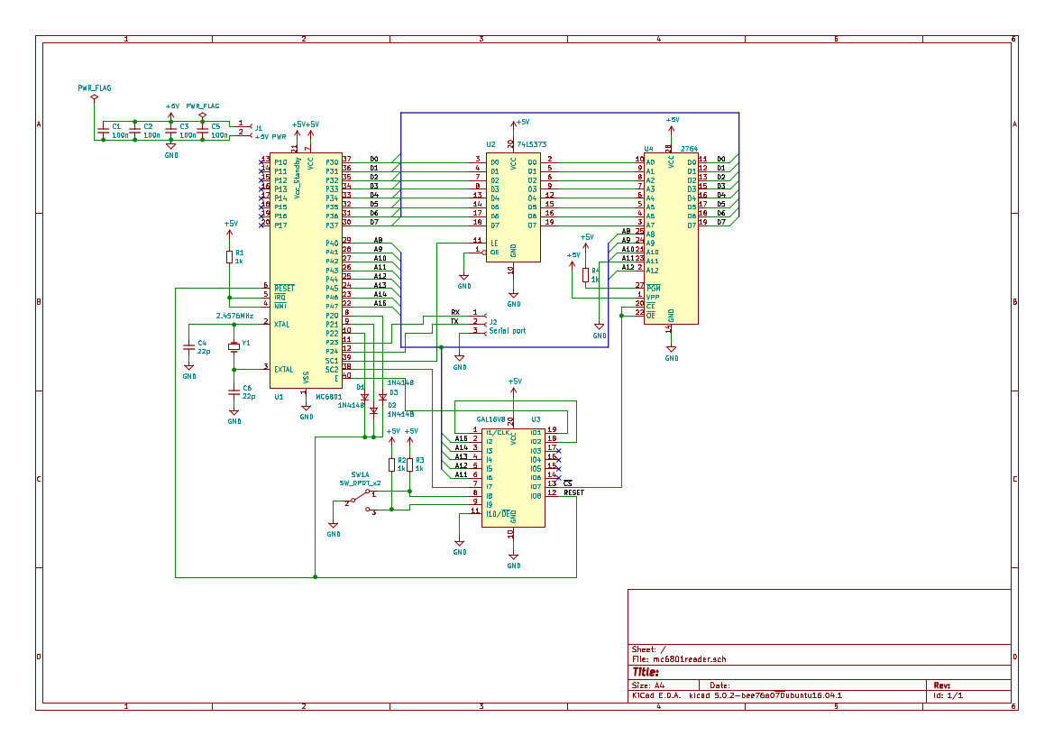
A schematic has been created in KiCAD and a breadboard circuit. Possibly a layout is created as well.

A mockup was created on a breadboard and a small problem was detected in the PLD. New PLD code fixed that problem. It was also detected that 68701 is sufficently different from the 6801 to not work with this circuit. The reason is that the 68701 has the interrupt vectors in a different place when running in mode 0. The 6803, which is the romless variant of the 6801, does work identical to the 6801. As it turns out it works perfectly with the circuit above. One interesting thing is that there actually are ROM content in the ROM which seems to be at least potentially correct. At least the RESET vector is in the correct spot! So it seems the 6803 is just 6801 chips which has been discarded due to bad firmware!?
With the baudrate set to 4800 bps a 6803 or a 6801 processor gave us a ">" prompt in response to pressing the reset button. It was working!

The resulting dump of the Ericsson keyboard 6801 firmware contained some interesting strings!
