- Name: Mauricio Mutai
- PennKey:
mmutai
- You can see the original readme here (recommended).
- I implemented two animations: "Paw Metaballs" (intermediate) and "Electron Orbitals" (difficult).
- Taken from the original homework repo.
- This shader converts its fragment's coordinate to a
vec2in NDC space (origin at the center of the image). Thisvec2is fed through a series of functions in order to determine which color it should get, based on its proximity to certain shapes. - The extra credit performs some ray-marching to render 3D metaballs instead.
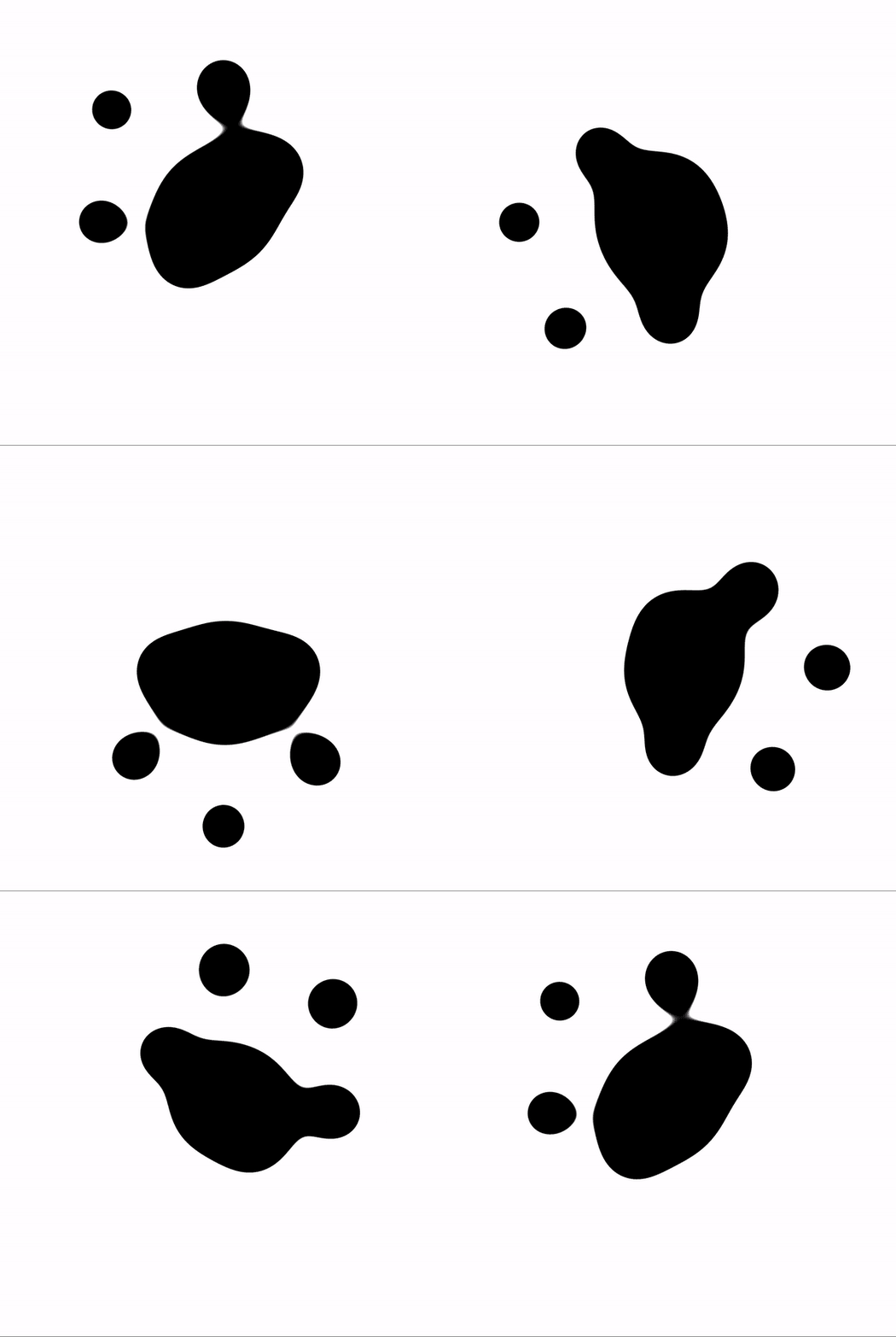
- As hinted by its title, the original animation appears to use metaballs to achieve the "blob" animation.
- I defined a
rawMetaball()function (please read the comment above this function for an important warning). It simply returns the metaball's radius divided by the distance from the input positionpto the metaball's center.- This function has the basic property of having a high value when
pis inside the metaball, and low whenpis outside it. It is always positive.
- This function has the basic property of having a high value when
- From observing the original animation, I inferred the following:
- There is one metaball in the center, and eight metaballs moving towards and away from the center periodically.
- The moving metaballs seem to have a sinusoidal function controlling their distance to the center.
- Each moving metaball is offset (in terms of where it is in its animation) relative to its neighbors.
- Since everything looks pretty uniform, this offset can be inferred to be
2 * PI / 8, if we define it in terms of an angle in a circle.
- Since everything looks pretty uniform, this offset can be inferred to be
- Using this information, I defined
aniMetaball(), which computes a moving metaball's center given two parameters: the directiondirin which it is moving, and its time offset. It then returns the result of a call torawMetaball()using the computed center.- More specifically, we compute a time-dependent
distvalue. This is the distance from the origin alongdir. distis computed usingcos()with an adequately scaled time variable. The output ofcos()is mapped to the range[0, 1], since the original animation doesn't seem to have the moving metaballs move past the center (which would be accomplished with negativedistvalues)- The center is then simply
dist * dir.
- More specifically, we compute a time-dependent
- For a given pixel with position
p, we sum the return values of one staticrawMetaball()and eightaniMetaball()calls to which we passp. This gives us ametaSum. If thismetaSumis above a threshold, then the pixel is said to be in a metaball (which one, we do not know).- In order to avoid aliasing/blockiness, we don't just return black or white. Instead, we compute the difference between
metaSumand the threshold, and use this value (fed through asmoothstep()with range[0, BLEND_EPSILON]) to blend between white and black.BLEND_EPSILONcan be tweaked to exaggerate this effect.
- In order to avoid aliasing/blockiness, we don't just return black or white. Instead, we compute the difference between
- Due to some structural changes described below, I chose to implement this extra credit on a separate shader:
- This modifies the metaball functions to be 3-dimensional instead. For each pixel with a 2D position
p, we ray-march as follows:- The ray origin is
(p.x, p.y, -0.5). - The ray direction is
(0, 0, 1). - We take fixed steps of size
0.01. - At each step, we compute
metaSum. If it is above our threshold, we stop marching.
- The ray origin is
- The reason for switching to 3D is to allow us to get normals. Normals can be rendered by uncommenting only
#define NORMALS.- The normal is computed using the gradient method described in this paper. The metaball function is sampled six times, such that each time, it's sampled at a point that's a small epsilon away from the "intersection" point on one dimension. These values are used to approximate the gradient and normal at that point.
- Another rendering mode uses Shadertoy's included cubemaps. The cubemap is sampled using the normal. This can be activated by uncommenting only
#define CUBEMAP. - Finally, we can use the normals in a more conventional way for Lambert + Blinn-Phong shading. This can be activated by uncommenting only
#define BLINN_PHONG. - In order to showcase the shading better, the background is now dark gray.
- The anti-aliasing blending is still done by projecting the "intersection" point onto the
Z = 0plane and re-computing themetaSum. The same blend as the 2D case is then performed.
- Taken from the original homework repo.
- This shader converts its fragment's coordinate to a
vec2in NDC space (origin at the center of the image). Thisvec2is fed through a series of functions in order to determine which color it should get, based on its proximity to certain shapes.
- I noticed the original animation had one base ellipse animation, which is then repeated with slightly different parameters in order to create the overall animation. So I tried to create a single ellipse animation.
- This is handled by
getEllipseColor(). This is a slightly misleading name, because it really is used to draw circles.- The aim of this function is to return a color as follows:
- Red, if the point is "on" the circle.
- White, if the point on the moving white point (see reference image).
- Blue otherwise.
- We find the angle
angleof the input positionpusingatan(). - We compute the point on the circle with a fixed radius of 1 and angle
angle. This could be accomplished by just normalizingpas well. - We compute a time-dependent
angleLimitusing a cosine. The idea is that points with an angle "beyond"angleLimitare not on the circle. This creates the effect of the white moving circle "tracing" the red ellipse.- Conveniently,
cos()andatan()return the same range of values ([-1, 1]). This made it easy to compare them initially, but an additional complication was added later. - Note I say the angle is "behind"
angleLimitinstead of just less thanangleLimitbecause the definition of "behind" changes over the animation.
- Conveniently,
- We use
angleLimitto compute the position of the moving white dot. - We are noe ready to return a color:
- If
pis within a certain distance of the moving white dot, we return white. - If
pis within a certain distance of the point on the circle ANDangleis "behind"angleLimit, we return red. - Otherwise, we return blue.
- If
- In practice, we actually return the color above blended with the input
blendColordepending on how closepis to the white moving dot or ellipse. This is done to remove aliasing/blockiness from the image. More on this below.- If
pis "close" to the white dot, we either blend withblendColoror with the red ellipse color, depending on whether we are "behind" theangleLimit.
- If
- The aim of this function is to return a color as follows:
- The trick to making
getEllipseColor()draw ellipses instead of circles is to simply scale the input positionp. I initially attempted a more "pure" ellipse drawing function that would preserve line thickness along the ellipse, but I noticed the original animation itself has varying line thickness caused by the scaling.- The moving white dot is also clearly affected by this scaling effect in the original animation.
- As described above,
getEllipseColor()draws a circle where the white moving dot moves back and forth, "tracing" the full circle when going in one direction, and "erasing" it as it goes in the other. - However, the original animation has the white moving dot going only in one direction.
- To fix this, I introduced a
goingBackboolean variable.goingBackis computed so as to look like a square wave with 50% duty cycle and frequency of 2PI. This is accomplished withmod(adjTime, 2.0 * PI) > PI, whereadjTimeis a scaled time variable.- This makes
goingBackfalse for the first half of the animation, and true for the second half. - If
goingBackis false, the function behaves like above. If it is true, then we flip the sign of theadjTimeused to computeangleLimit. We also remove an offset of-PIfromadjTimethat is usually added to makeadjTimestart on a rising part of the cosine curve.- These changes to
adjTimeessentially shift it to the correct part of the cosine curve such thatangleLimitincreases again for the second half of the animation, instead of decreasing.
- These changes to
- If
goingBackis true, we also negate theisBehindboolean that says whetherangleis "behind"angleLimit.
- In order to make the white moving dot spend more time closer to its poles (i.e. the points where the ellipse is either not fully drawn or fully drawn), I use a Perlin gain function with
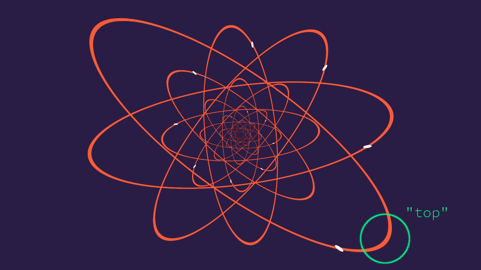
gain < 0.5. This gives the desired effect of spending more time at the edges of the[0, 1]range, rather than the middle. - I noticed the white moving dot does not start at the "top" of the ellipse, but it is instead offset by a little bit (see image below).
- This can be fixed by adding a constant offset (say,
LIMIT_ORIGIN, orL_O, for short) toangleLimitto shift its range to[-PI + L_O, PI + L_O]. However, this makes the comparison withangle, which is in[-1, 1], not work anymore. Why? AssumingL_O < 0, the region[PI + L_O, PI]ofangleis visually in the[-PI + L_O, -PI]range ofangleLimit, but not numerically. The solution to this is explained with more depth in the comments forisBehindAngleLimit(), but it essentially treats the[PI + L_O, PI]region ofangleas a special case.
- Having a correct
getEllipseColor(), we can create different ellipses by transforming the pointppassed to it. Note that, if we want to transform the ellipse with a transformationT, we really need to transformpwithinv(T), just like in ray-intersection tests or SDF scenes. - By scaling
p, we scale the resulting ellipse (we use this to make ellipses from the circle in the first place).- The original animation seems to scale the Y axis of the ellipses over time to change them from a circle (when the ellipse is not drawn at all) to an elongated ellipse (when it is fully drawn). I reproduced this effect using a cosine function with the same frequency as the one dictating the movement of the white moving dot, in order to keep the movements synchronized.
- In addition, I perform some additional scaling on both the X and Y axes in order to make the ellipse as a whole bigger when it's fully drawn. This is because, if I keep a constant scale to the ellipses, it either looks too small when fully drawn, or looks too big when not drawn (the white dots go off the screen). I suspect the original animation did this as well, since I noticed it has the same aspect ratio as Shadertoy (a different aspect ratio could alleviate this problem, in theory).
- By rotating
p, we... rotate the ellipse. The original animation clearly does this.- Again, we control this using a cosine function with the same frequency as the one controlling the white moving dot.
- In the original animation, some ellipses rotate clockwise (the bigger ones), while others rotate counterclockwise. This is also handled by having the rotation speed be a modifiable parameter for each ellipse.
- Translating
pis possible, but doesn't seem to be done in the original animation. - An
ellipse()function was created that handles transformingpgiven parameters to specify rotation speed, initial rotation offset, and desired scale.
- We can now animate mutliple ellipses, but how should we combine the
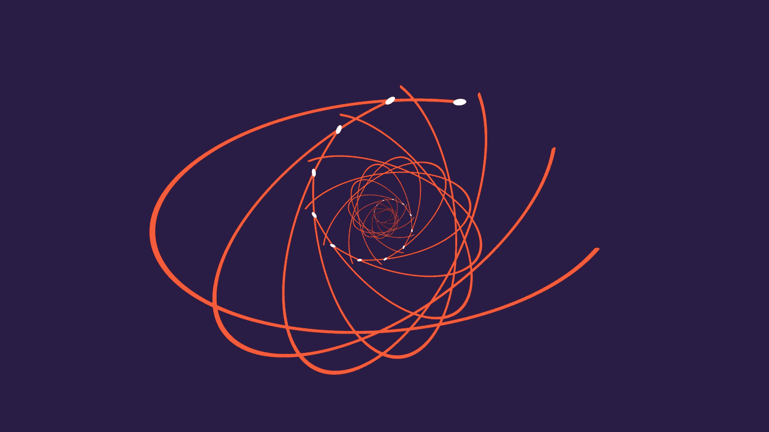
ellipse()calls? - The original animation seems to layer the ellipses such that the smaller ellipses get drawn on top of bigger ellipses (see example below):
- I thought it would be helpful to introduce a
hitGeometryboolean output togetEllipseColor()andellipse()that tells us if the pointphit geometry, that is, was close enough to the ellipse or white moving dot. - Naively making
ellipse()calls from small to big ellipses and stopping whenhitGeometryis true works for creating the correct layering effect, but breaks the color blending logic, because it has no information of what color is behind the ellipse/white dot being colored. - Instead, we can initialize
blendColorto the background blue color and go from big to small ellipses instead. If we hit geoemetry, we updateblendColorwith the return value ofellipse(). This essentially propagates the correct background color inblendColoruntil the smallest/topmost ellipse that needs it.
- The original animation seems to contain 20 or so ellipses. I added 12 ellipses, starting from the biggest one. I have two reasons for not going all the way to 20:
- I seemed to be getting diminishing returns from each ellipse I added. The smaller ellipses don't add that much to the animation.
- The assignment says we don't need to be pixel-perfect, and that it's more about understanding the ideas used to render the animation. I hope I showed that I do understand the ideas, and that with additional time, I could have placed 20 or more ellipses.
- Enable by uncommenting
#define FLIP. - In
getEllipseColor, we scale the Y axis during the middle of the animation to make it appear as if the ellipses are rotating about their local X axes. - We use
modAdjTime = mod(adjTime, 2.0 * PI)to get a value to tell us where we are in the animation, regardless of how many animation cycle have been performed. - We limit the flipping animation to
modAdjTimein[PI * 0.5, PI * 1.5]so that it only happens when the ellipse is mostly drawn. - We scale Y by dividing it by
cos(modAdjTIme * 4.0). UsingmodAdjTimeas the time parameter ensures it's consistent across animations. Multiplying it by 4 has two desired effects: it makes the flip happen multiple times per animation cycle, and it ensures the scaling begins and ends with a identity scale (i.e. scaling by 1), since the animation starts atPI * 0.5(PI * 0.5 * 4 = PI * 2, socos()returns 1) and ends atPI * 1.5(PI * 1.5 * 4 = PI * 6, socos()returns 1).- The 4 factor can be tweaked, but this requires changes to the extremes of the
[PI * 0.5, PI * 1.5]range, unless you "tweak" it to another multiple of 4.
- The 4 factor can be tweaked, but this requires changes to the extremes of the
- Enable by uncommenting one of
#define ADD_LIGHT_BLENDand#define ADD_DARK_BLEND. - This was a bit of an experiment on "tone mapping" (really gamma correction) and additive blending. The default shader uses interpolative blending. This reproduces the effect in the original animation of ellipses completely occluding ellipses behind them. However, we could use additive blending instead to make our pixels brighter if they overlap more than one ellipse.
- The gamma correction formula was taken from Wikipedia.
- There are two modes: the "light blend", and the "dark blend". Both have additive blending, but the dark blend exaggerates the bright overlapping areas more, at the cost of making the overall image significantly darker.
- Enable by uncommenting
#define PULSATING_COLOR. - Makes the red ellipse and white moving dot's colors change over time. This is done by interpolating between two colors using a
cos()scaled to[0, 1].- The time parameter to this
cos()is scaled so that the cosine has a frequency that's not an integer multiple of the main frequncy (the one that dictates the moving dot and ellipse rotation). This makes it so the color pattern is flipped every other cycle (e.g. when at the top of the screen, the moving dot will have one color on one cycle, and another color on the next cycle).
- The time parameter to this
- My favorite combination is turning on flip, dark blend, and pulsating color. Just flip and dark blend is good too, I think.
- Stephen Whitmore's article on 2D metaballs
- Jamie Wong's article on 2D metaballs
- Wikipedia article on ellipses (although not much of it is left in the current implementation, due to the shift to spheres)
- Wikipedia article on gamma correction
- Pandoc, for converting Markdown to PDFs


