"IoT Made Easy!"
Devices: | PIC16F1619 | PIC18F47K40 | MICRF112 | MICRF220 | MICRF219A|
Features: |Sub-GHz|
THE SOFTWARE ARE PROVIDED "AS IS" AND GIVE A PATH FOR SELF-SUPPORT AND SELF-MAINTENANCE. This repository contains example code intended to help accelerate client product development.
For additional Microchip repos, see: https://github.com/Microchip-MPLAB-Harmony
Checkout the Technical support portal to access our knowledge base, community forums or submit support ticket requests.
- Introduction
- Bill of materials
- Hardware Setup
- Software Setup
- MCC Melody Configuration
- Board Programming
- Run the demo
This application demonstrates the functionality of the MICRF TX CLICK module with a PIC16F1619 microcontroller and the MICRF RX CLICK module with a PIC18F47K40 microcontroller using Amplitude Shift Keying (ASK) modulation.
-
The MICRF TX module transmits an incrementing counter value via ASK modulation at a frequency of 315 MHz.
-
This transmission is received by the MICRF RX module on the receiver side.
-
The received data's Received Signal Strength Indicator (RSSI) value and the total number of packets received are displayed on an LCD screen.
-
By pressing the user button S1, the LCD switches to display engineering data, which includes error counts, CRC (Cyclic Redundancy Check) information, protocol failures, and buffer overflow statistics.
| Hardware Required | Description | Quantity |
|---|---|---|
| DM164137 | Curiosity Development Board. | 1 |
| PIC16F1619 | Change MCU on DM164137 for MICRF TX CLICK. | 1 |
| MICRF TX CLICK | ASK/FSK Transmitter (315Mhz). | 1 |
| DM160228 | Explorer 8 Development Kit. | 1 |
| PIC18F47K40 | Change MCU on DM160228 for MICRF RX CLICK. | 1 |
| MICRF RX CLICK | ASK/OOK Receiver (315Mhz). | 1 |
| ICD3 | In-Circuit Debugging for DM160228 | 1 |
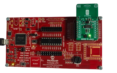
Step 1 - Replace the default MCU of Curiosity Development Board with PIC16F1619.
Step 2 - Connect the Jumper J12 to 3.3V/5V based on the MCU(here PIC16F1619 has Operating voltage range 2.3V to 5.5V).
Step 3 - Connect the MICRF TX CLICK Board to the MIKROE BUS Connector as shown below.
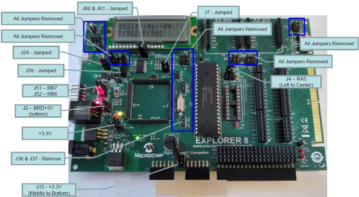
Step 1 - Replace the default MCU of Explorer 8 Development Kit with PIC18F47K40.
Step 2 - Connect the MICRF RX CLICK Board directly into J35 Jumper (MIKROE BUS Connector).
Step 3 - Power Explorer 8 from J1, the 9V power adapter, not from USB.
Step 4 - Verify all the Jumper connection of the Explorer 8 Development Kit as shown below.
-
- Version: 6.20
- XC8 Compiler v2.46
- MPLAB® Code Configurator v5.3.0
- PIC12-16F1xxx_DFP v1.3.90
- PIC18F-K_DFP v1.7.134
| Tip | New users of MPLAB Code Configurator are recommended to go through the overview |
|---|
-
Configure the following components in MCC Melody configuration as shown below.
-
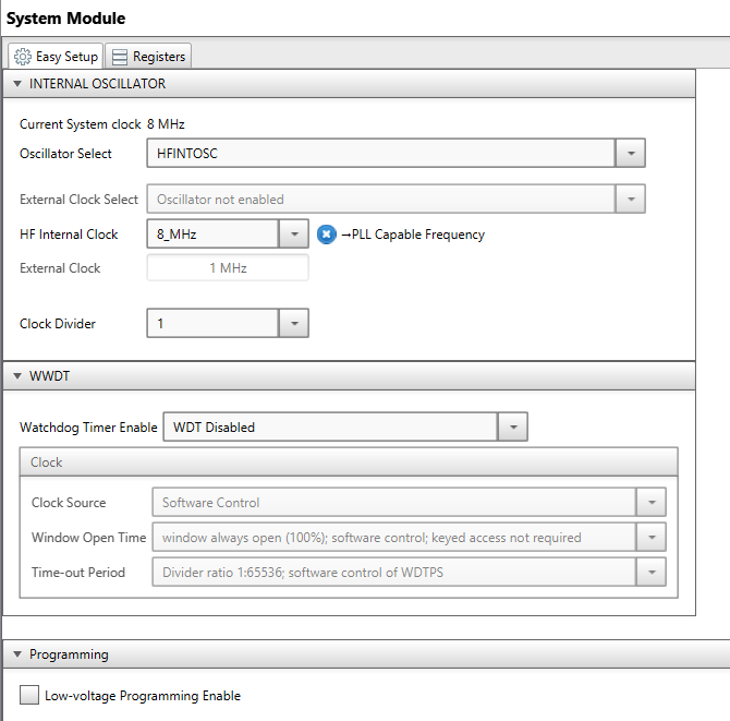
Configure the INTERNAL OSCILLATOR as shown below.
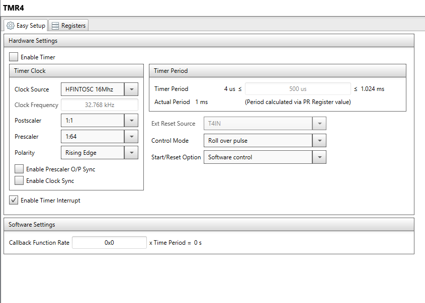
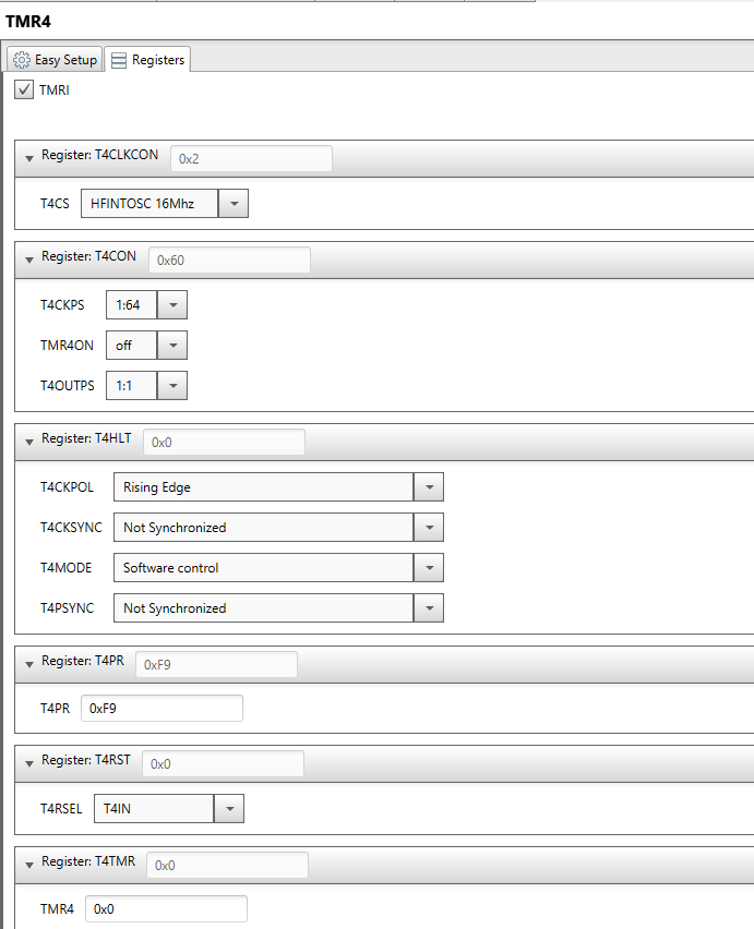
- Configure the TMR4 as shown below.
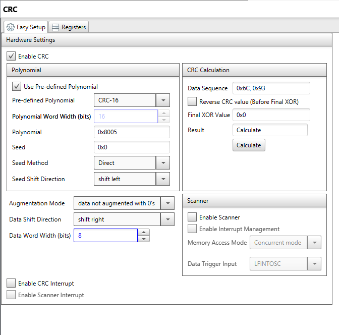
- Configure the CRC as shown below.
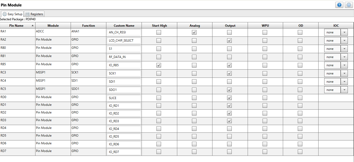
- Configure the Pin Modules as shown below.
-
Click on Generate once all the components are configured.
-
Connect the USB for programming the Device from MPLAB X IDE.
-
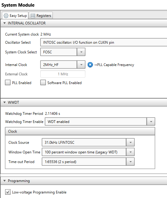
Configure the following components in MCC Melody configuration as shown below.
-
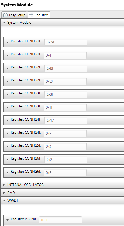
Configure the System Module as shown below.
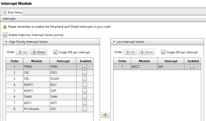
- Configure the Interrupt Module as shown below.
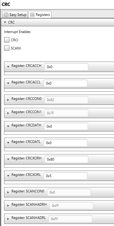
- Configure the CRC as shown below.
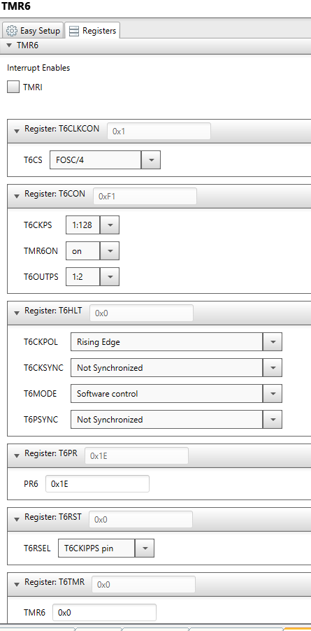
- Configure the TMR6 as shown below.
- Configure the ADCC as shown below.
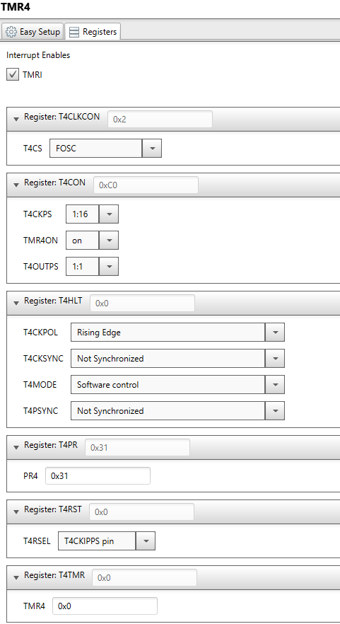
- Configure the TMR4 as shown below.
- Configure the Pin Modules as shown below.
-
Click on Generate once all the components are configured.
-
Connect the IDC 3 In-Circuit Debugger to program the device..
- The Precompiled hex file is given in the hex folder. Follow the steps provided in the link to program the precompiled hex file using MPLABX IPE to program the pre-compiled hex image.
The application folder can be found by navigating to the following path:
-
"Transmitter/MICRF_TX.X"
-
"Receiver/MICRF_RX.X"
Follow the steps provided in the link to Build and program the application.
-
After programming the board, the expected application behavior is shown in the below video.
-
The MICRF TX CLICK is a transmitter which sends the incremented counter value and whenever the data is transmitted the D7 led glows.
-
The MICRF RX CLICK is a receiver which receives the data from the MICRF TX and displays the data received along with RSSI value.
