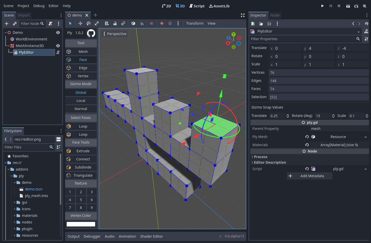
Godot plugin for in-editor box modelling for gray boxing or prototyping 3d levels.
The main branch is active development for Godot 4. See releases for stable releases.
See demos on youtube.
Join our Discord
- Copy the contents of the plugin directory in this repository into your
addonsfolder for your Godot project. - Activate the plugin in your project settings.
Create a PlyEditor node as the child of a MeshInstance or CSGMesh and select it.
There are four selection modes:
Shift + Clicking will add and subtract from the set of selections.
Alt + Clicking in edge or face mode will select loops.
And three gizmo modes:
- Global - Translate/Rotate/Scale along global coordinates
- Local - Translate/Rotate/Scale along local model coordinates
- Normal - Translate/Rotate/Scale along coordinates aligned to the average normal of the selected geometry
The gizmo behaves much like the standard Godot gizmo; however, it includes scale handles by default.
- Translate Axis: Arrows
- Translate Plane: Squares
- Rotate Around Axis: Arcs
- Scale Axis: Cubes
- Scale Plane: Triangles
The inspector includes translate/rotate/scale tools for fine-tuning, respecting the selected gizmo mode.
There are tools for each selection mode:
-
Mesh
- Mesh Tools
- Subdivide: Subdivide all quads/tris into four quads/tris
- Triangulate: Triangulate all faces using an ear clipping algorithm
- Invert Normals: Inverts the normals of all faces
- Mesh Utilities
- Export to OBJ: Exports the selected mesh to an OBJ file
- Currently exports basic geometry, excluding normals, materials, etc
- Quick Generators
- Plane: Generate a two-sided unit plane
- Cube: Generate a unit cube
- Generate: Opens a modal for more advanced generation
- Plane: Generate a plane with a specified size and subdivision count
- Cube: Generate a cube with a specified size and subdivision count
- Isosphere: Generate an isosphere with a specified radius and subdivisions
- Cylinder: Generate a cylinder with a specified radius, depth, and circle vertex count
- Export to OBJ: Exports the selected mesh to an OBJ file
- Mesh Tools
-
Face
- Select Faces
- Face Tools
ctrl-eExtrude: Extrudes the selected face(s) along their mean normal by 1 unit- Connect: Remove the two selected faces, creating a new face between edges. Tries to choose an edge pairing that works.. but not always.
- Subdivide: Subdivide a quad or a tri into 4 quads or 4 tris
- Triangulate: Triangulates a face using an ear clipping algorithm
- Paint Faces: Moves the selected face to the chosen surface, allowing multiple materials per mesh. Assign materials to the parent MeshInstance or in the Ply Editor materials array.
-
Edge
-
Vertex
- None, yet!
Collision meshes are updated if there is a CollisionShape child of the parent MeshInstance node at $StaticBody/CollsionShape. This is the default naming if you use the Create Trimesh Static Body tool.
Meshes are meant to only be oriented manifolds. Some properties:
- Each edge has one or two faces (although we generally use precisely 2)
- All of an edge's faces have compatible orientation -- that is, the edge origin and destination are in the opposite order for opposite faces.
Ply uses a winged edge representation for edges but omits counterclockwise navigation:
omitted
left ccw        right cw
         \     /
          \   /
           \ /
            o destination
            ^
            |
left face   |   right face
            |
            o origin
           / \
          /   \
         /     \
left cw          right ccw
                 omitted
Given this representation, a few limitations occur that are representable in other tools:
- One cannot arbitrarily extrude edges into one-sided faces, or one edge would be incident with >2 faces.
- One cannot flip individual faces, as the faces would no longer have compatible orientation.
Feel free to contribute! Both issues and pull requests are very welcome.
Feel free to contact me on the godot discord server, where my name is hints
