Power Control Board for microcontroller projects, designed at OPEnS Lab OSU.
Go to Hypnos Wiki for more info and build guide.

The OPEnS-Hypnos board is a simple, low-cost circuit board that can be attached to an Adafruit Feather M0 microcontroller and a DS3231 real-time clock breakout board to enable shutting off power to the microcontroller until a timed or sensed event wakes it up. In the early time of development, the Feather needs to be shut down completely due to the inefficient deep sleep firmware. A circuit was designed to keep the state of the system, and a real-time clock can change the state and wake everything back up. After Adafruit released new firmware for Feather M0 that allows microamp sleep current, complete shutdown of the Feather seem unnecessary. However, during deep sleep, the 3v3 volt regulator is still providing power to other peripherals. MOSFET circuitry is introduced in HYPNOS to cut down power to peripherals. Additional RTC and microSD for accurate timekeeping and data logging.
Hypnos V2.xPower + RTC + microSD with FeatherWing footprint. Allow control on 3.3V and VUSB rail. Using MOSFET circuit and Feather deep sleepHypnos V3.xUpgraded from regular Hypnos. Can control one more rail of higher voltage (9-24V) at max 2.0 A continuousHypnos V3.3.lbrEagle library that has all of the components the Hypnos contains such as the push button, MOSFET footprints, Feather pinout, etc.
- Controlled 3v3 Rail (0.4 A continuous) and 5V Rail (0.5 A continuous from USB)
- RTC DS3231 with TCXO
- Back up power CR1220 for RTC
- Micro SD slot
- RTC INTerrupt pin: GPIO 12
- 3.3V control pin: GPIO 5
- 5V control pin: GPIO 6
- SD chip select: GPIO 11
Show more
Any I2C device behind Adafruit I2C Multiplexer does not need to be powered. We have tested the system with the Multiplexer turn off without the I2C line hanging.
Remember to power the 3.3Rail before initializing/communicating with uSD card, RTC, and I2C devices.
-
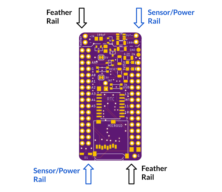
Feather Rail: connects directly to your Feather. Anything connected to this rail will have their power constantly on and only turn off in Shipment Mode. Power Control will not work on this rail.
-
Sensor/Power Rail: connects directly to your sensor board which you wish to turn the power on/off. The 5VUSB pin and 3V pin are controlled within the rail. Digital and Analog pins on this rail connect directly to the Feather. Extra 3V|5V with LEDs are for an external plug for prototyping.
-
3v3 rail: Set
PIN 5of the Feather to LOW for closed circuit (conduct), otherwise, the pin is pulled HIGH for open circuit (not conduct). -
5V rail: Set
PIN 6to HIGH for closed circuit (conduct), the PIN is pulled LOW for open circuit -
+V rail: This pin shares control with the 5V rail. Set
PIN 6to HIGH for closed circuit (conduct), the PIN is pulled LOW for open circuit
SD card: Chip Select PIN 11, required 3.3Rail power, normal SPI communication
RTC DS3231: INT-errupt PIN 12, required 3.3Rail power, I2C pull up attached to 3.3Rail
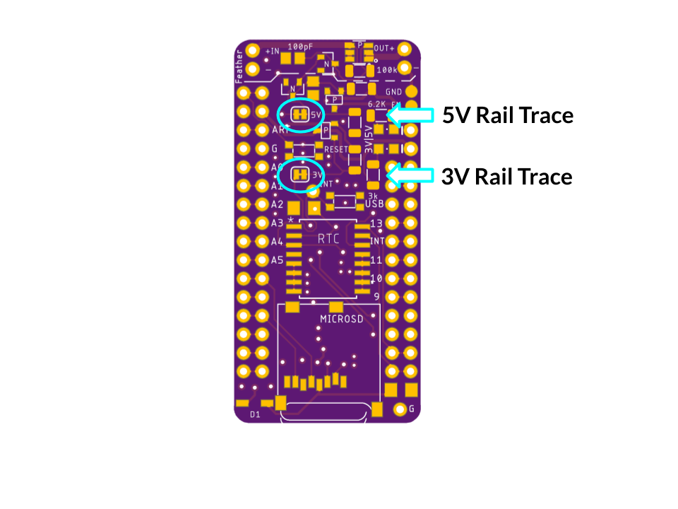
Note: If you need a GPIO pin AND you are not using one of the 3V or 5V rails, you are able to free the GPIO pin for use by cutting the trace of the rail that is not used.
Short the GND and EN will turn off the 3.3V regulator temporarily. The male header + Jumper cap is a great combination. Once the jumper cap is removed, the Feather will boot up normally and resume operation.
- 5Vrail can go up to 1.2A if external 5V is connected directly to Feather USB pin
- The LEDs are low power (rated at 2mA instead of 20mA)
- I2C line pull up is attached to 3VRail