What: a small DIY board that automatically switches on the popular JBD BMS, effectively switching on the EBike/EScooter, when there is motion / vibration.
A timeout of 2 minutes, if no motion is detected, will automatically switch off. Also, a wireless communication accepts a command (for instance, sent from a display) to switch off.
Avoids the need to install a mechanical switch and also adds the safe timeout that automatically switches off the EBike/EScooter.
On the next picture, the DIY board:

- Switches on the EBike/EScooter by detection motion: JBD BMS switches on when there is motion of the EBike/EScooter.
- Automatic switches off the EBike/EScooter: JBD BMS switches off after 2 minutes, when there is no more motion.
- Ultra low power: espected to use only 0.007 watts when JBD BMS is switched off (will take 8 years to discharge a 500Wh battery).
- Cheap and easy to DIY: costs 10€ in materials and needs only soldering 10 wires.
- Wireless communication with other boards: an EBike/EScooter display board can send a command by wireless, to switch off immediatly the JBD BMS.
You will need to buy (I bought all the components from Aliexpress):
-
Download the CircuitPyhton binary to your board.
-
Connect the ESP32-S2 board in bootloader mode to your PC with a USB-C cable. On Linux I use this command to flash the CircuitPython:
esptool.py write_flash 0 adafruit-circuitpython-lolin_s2_mini-en_US-8.1.0-beta.1.bin
- Follow the CircuitPython guides to make sure your board is working, like make some print("hello world") code.
Connect the ESP32-S2 board to your PC using a USB-C cable. A USB flash disk should apear. Copy all the files and folders inside firmware folder, to the USB flash disk. Unmount the USB flash disk from your PC, remove the USB-C cable. Next time you power up the ESP32-S2 board, the firmware will run, like when connecting again the USB-C cable. See the CircuitPyhton basic tutorial if you have questions.
The DC-DC step-down converter, converts the battery voltage to 3.3V. The 3.3V will power the ESP32-S2 board and the ADXL345 module board.
This means the ESP32-S2 will always be running, althought in deep sleep mode, ultra low power, while waiting for the motion pin signal change, that is the output of ADXL345 module.
The ADXL345 module is powered also by the 3.3V and is ultra low power. With motion, the ADXL345 INT1 pin will change.
The relay signal from the ESP32-S2, will have a 3.3V volts to switch on the relay and 0V to switch off the relay (not that 5 connections to the ESP32-S2 are needed, otherwise the 3.3V signal to relay will not be enough to turn it on, as the relay coil may use a good amount of current that can only be provided by the sum of a few ESP32-S2 pins). The relay open switch pin will be connected to the JBD BMS switch pins.
Following the schematic, build the board as the following images.
I did solder the ADXL345 board on the back of the ESP32-S2 board. I used kapton tape to make sure I isolated the back of both boards from touch electronically each other. I also used dual face tape.
I used 6 header pins to solder the pins directly, and avoid the need to wires wires. Still, 2 wires are needed: 3.3V (VCC) and GND (black wire):

Top save the most power possible, I removed the little resistor near the LED and this way there are no energy used by the LED. I also removed the 5 pin little integrated circuit, that is 5V -> 3.3V voltage regulator - note that once you remove it, the board will only work when you provid the 3.3V externally, it will not work any more from the USB-C:

Wire the 3.3V and GND from the DC-DC converter to the ESP32-S2 board. Also wire the relay to the ESP32-S2 pins:

To test if everything is working, measure the voltage with the multimeter between the GND and the 3.3V on the ESP32-S2 board - it must be near 3.3 volts. Then measure between the GND and the relay switch wire - should be near 3.3 volts when the ESP32-S2 board detects motion, but after the timeout, it will be 0V.
NOTE: you can use the JBD BMS app to see the switch state. You will need to enable the switch feature on the app, otherwise it will never switch on.
Finally, use some good tape to cover all the board.
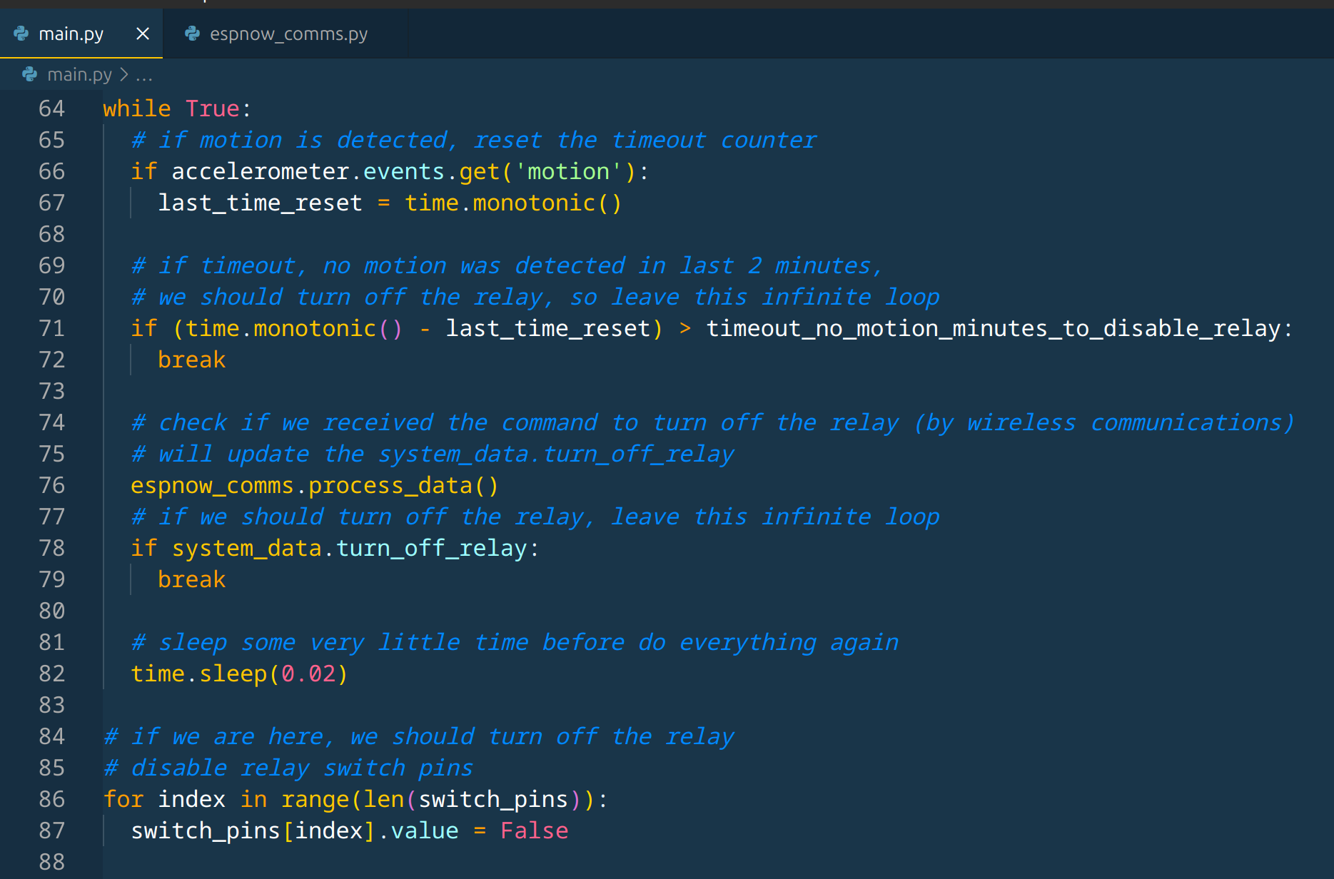
The main firmware is on the main.py file. espnow_comms.py file has the code to received by wireless (for instance, sent by a display) a command to turn off the BMS.
The lib folder has the needed Pyhton libraries, like the adafruit_adxl34x that communicates with the ADXL345 module.
The main firmware:
- Starts by turn the relay switch pins to high state / 3.3 volts, as needed to switch on the relay, that in turn will switch the BMS.
- Initialize the ADXL345 and enable the motion detection. The ADXL345 will change the INT1 pin when it detects motion.
- A PinAlarm is created, this will wakeup the ESP32-S2 everytime the ADXL345 INT1 pin changes.
- The code inside the while True will run continuously until the timeout happens (no motion detected during timeout_minutes_to_disable_relay minutes - 2 minutes) or the wireless command to switch off the relay is received.
- Next code switches off the BMS by turning the relay switch pins to logic 0 / 0 volts.
- Finally, ESP32-S2 enters in deep sleep mode (ultra low power), keeping the relay switch pins in the state to keep the BMS switched off. The motion alarm will be active meaning the ESP32-S2 will then wake up when detection motion, and the firmware will run again starting from the begin.


