
The PIC18F47Q10 features Three 8-bit Timers/Counters and two MSSP modules, which can be configured in SPI mode. In this demo, the TMR2 is used as 10kHz clock for SPI, configured as master with 2 slaves (RC6 pin ->SS1 and RC7 pin ->SS2).
- Technical Brief Link (linkTBD)
- PIC18F47Q10 Product Family Page
- PIC18F47Q10 datasheet for more information or specifications.
- MPLAB® X IDE 5.30 or newer (microchip.com/mplab/mplab-x-ide)
- MPLAB® XC8 2.10 or newer compiler (microchip.com/mplab/compilers)
- PIC18F47Q10 Curiosity Nano (DM182029)
- An oscilloscope or logic analyzer
The PIC18F47Q10 Curiosity Nano Development Board (DM182029) is used as the test platform.

The following pin configurations must be made for this project:
| Pin | Configuration |
|---|---|
| RC3 | Digital output SCK |
| RC4 | Digital input SDI |
| RC5 | Digital output SDO |
| RC6 | Digital output SS1 |
| RC7 | Digital output SS2 |
- Calculate the SCK frequency using the formula
frequency = 1/Timer2Period/2. - For example for 10kHz
frequency = 1/50μS/2 = 10 kHz, this meansTimer2Period = 50μS. - Build demo firmware, make and program the generated code onto the PIC18F47Q10 Curiosity Nano.
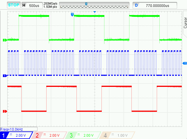
- Run the code, connect an oscilloscope or logic analyzer to the pins:
- RC3 pin - SCK -> Channel 1 (blue)
- RC6 pin - SS1 -> Channel 2 (red)
- RC7 pin - SS2 -> Channel 3 (green)
- In the screenshot below, the SCK frequency is 10 kHZ (blue signal).

This project showcases how easy it is to use the TMR2 of PIC18F47Q10 as Alternate SPI clock.