This is an Arduino board package for the PADI IoT Stamp.
The package simply builds off of the Realtek Ameba Arduino package. Please install it beforehand.
Add:
https://github.com/gtalusan/PADIIoTStamp/raw/master/release/package_padiiotstamp_index.json
to your Arduino IDE and install the padiiotstamp package.
Install OpenOCD. The platform.txt assumes it lives in /usr/local/bin.
The platform.txt contains a menu to configure OpenOCD via the Arduino's Tools menu. If you don't see your OpenOCD compatible device in the drop down, you likely need to add a new menu item.
I accept patches.
NOTE: this has only been tested on macOS Sierra. Buyer beware.
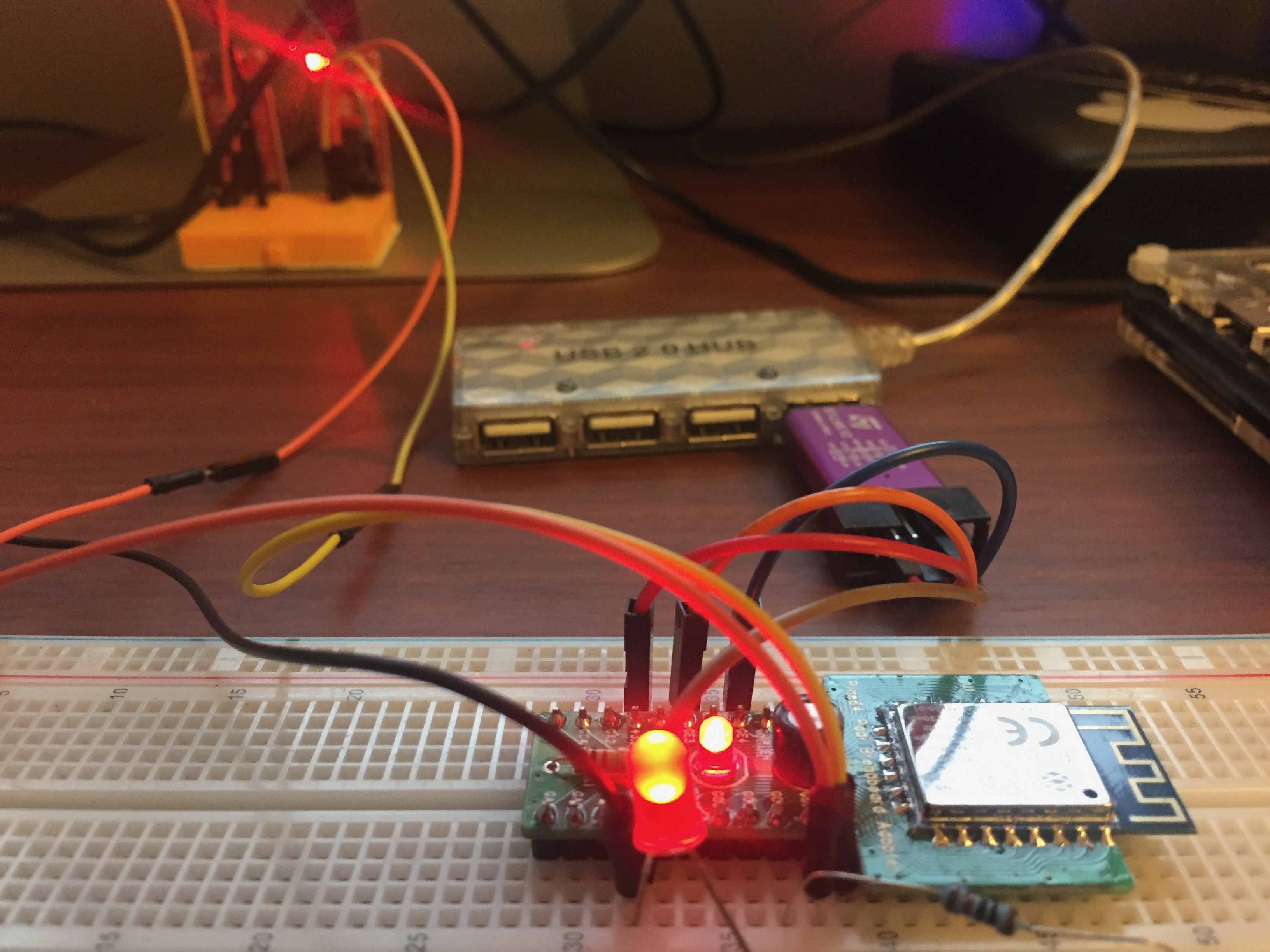
The typical Blink sketch runs great. I have the LED wired to GC1.
// the setup function runs once when you press reset or power the board
void setup() {
  // initialize digital pin LED_BUILTIN as an output.
  pinMode(LED_BUILTIN, OUTPUT);
}

// the loop function runs over and over again forever
void loop() {
  digitalWrite(LED_BUILTIN, HIGH);   // turn the LED on (HIGH is the voltage level)
  delay(1000);                       // wait for a second
  digitalWrite(LED_BUILTIN, LOW);    // turn the LED off by making the voltage LOW
  delay(1000);                       // wait for a second
}
UART pins are GB0 and GB1 at 38400 baud.
The Ameba IOT example ScanNetworks runs right out of the box:
ROM Version: 0.3

Build ToolChain Version: gcc version 4.8.3 (Realtek ASDK-4.8.3p1 Build 2003)

=========================================================
Check boot type form eFuse
SPI Initial
Image1 length: 0x3a88, Image Addr: 0x10000bc8
Image1 Validate OK, Going jump to Image1
BOOT from Flash:YES
SPI calibration
Find the avaiable window
===== Enter Image 1 ====elay start:0; Delay end:63
SPI calibration
Find the avaiable window
Baud:1; auto_length:11; Delay start:0; Delay end:63

load NEW fw 0
Flash Image2:Addr 0xb000, Len 220532, Load to SRAM 0x10006000
No Image3
Img2 Sign: RTKWin, InfaStart @ 0x10006049
===== Enter Image 2 ====
interface 0 is initialized
interface 1 is initialized

Initializing WIFI ...
WIFI initialized
MAC: 0:E0:4C:87:0:0
Scanning available networks...
** Scan Networks **
number of available networks:13
0) BELL902	Signal: -71 dBm	EncryptionRaw: WPA2 AES	Encryption: WPA2
1) BELL881	Signal: -83 dBm	EncryptionRaw: WEP	Encryption: WEP
2) doghouse	Signal: -85 dBm	EncryptionRaw: WPA2 AES	Encryption: WPA2
3) hogwarts	Signal: -89 dBm	EncryptionRaw: WPA2 AES	Encryption: WPA2
4) Rogers10444	Signal: -89 dBm	EncryptionRaw: WPA/WPA2 AES	Encryption: WPA2
5) BELL700	Signal: -89 dBm	EncryptionRaw: WPA2 AES	Encryption: WPA2
6) 869952	Signal: -91 dBm	EncryptionRaw: WPA/WPA2 AES	Encryption: WPA2
7) dlink-01D5	Signal: -91 dBm	EncryptionRaw: WPA/WPA2 AES	Encryption: WPA2
8) That Girl T	Signal: -93 dBm	EncryptionRaw: WPA2 AES	Encryption: WPA2
9) JROY2016	Signal: -95 dBm	EncryptionRaw: WPA/WPA2 AES	Encryption: WPA2
10) OnyxLion-guest	Signal: -95 dBm	EncryptionRaw: Open	Encryption: None
11) Venture Headquarters	Signal: -95 dBm	EncryptionRaw: WPA/WPA2 AES	Encryption: WPA2
12) BELL842	Signal: -95 dBm	EncryptionRaw: WPA2 AES	Encryption: WPA2
Works OK!
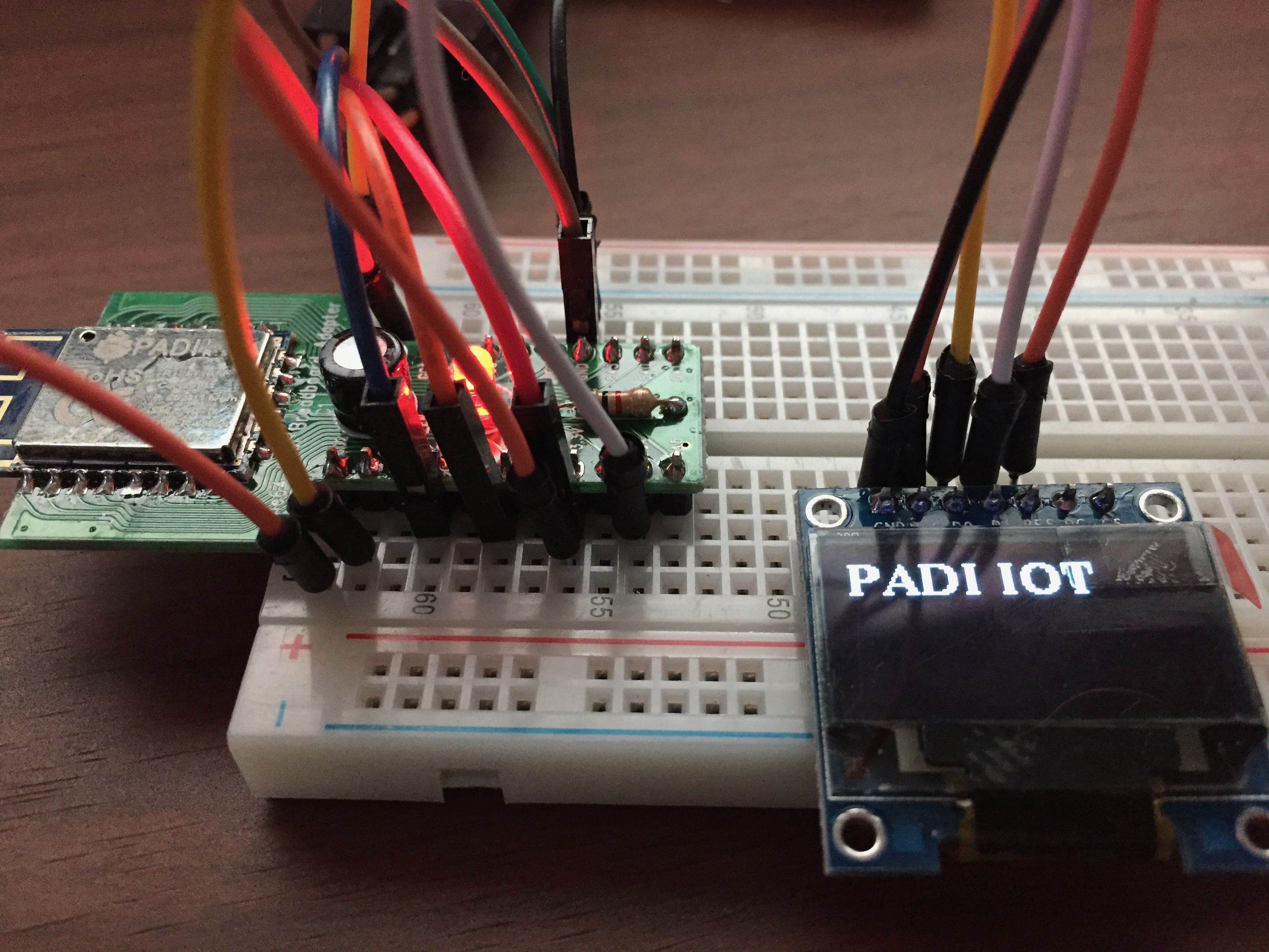
#include <U8g2lib.h>

U8G2_SSD1306_128X64_NONAME_1_HW_I2C u8g2(U8G2_R0, 11);

void setup(void)
{
	u8g2.begin();
}

void loop(void)
{
	u8g2.firstPage();
	do {
		u8g2.setFont(u8g2_font_ncenB14_tr);
		u8g2.drawStr(0,20,"PADI IOT");
	} while (u8g2.nextPage());
	delay(1000);
}

