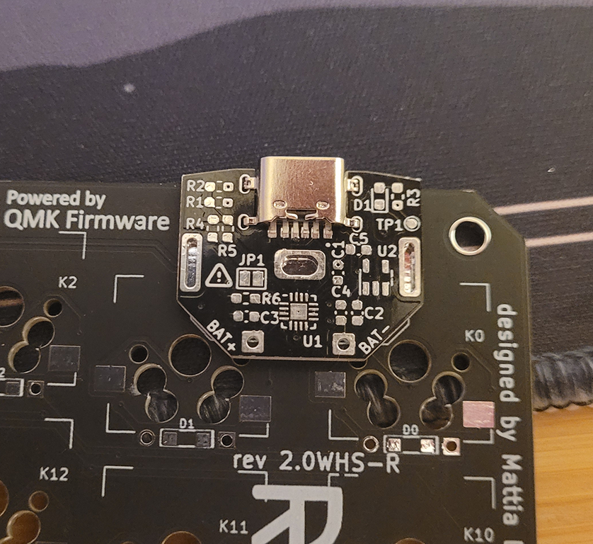
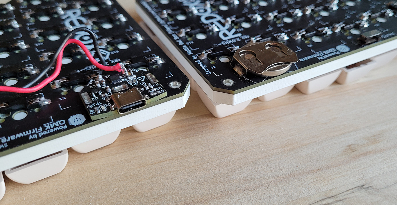
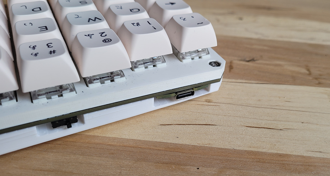
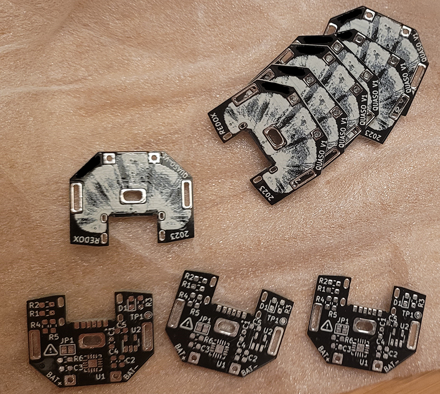
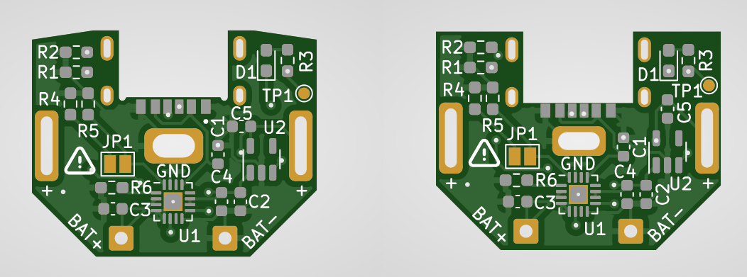
Project QUASO: Quick Usb Adapter for the wirelesS redOx. This PCB replaces the coin cell battery of a wireless Redox keyboard, it has a USB-C connector and circuitry to charge a LiPo battery. Gone are the days of buying disposable coin cell batteries for your wireless keyboard.
I really like my wireless Redox, however, I find that having to replace the coin cell battery is kind of annoying and wasteful. I could have just built a non-wireless Redox and changed the pro-micro to a Nice!Nano to get both wireless + rechargeable LiPo. But that would have been a waste, since it means building a brand new keyboard just to save on a few coin cells. Hence why I decided to design this mod.
See BUILD.md for the build and assembly instructions.
You can find here a 3D printed case that accommodates a 503035 LiPo battery.
The USB-C connector is only used to charge the battery, it doesn't transmit data.
Because the PCB replaces the coin cell battery holder, the keyboard's on/off switch doesn't disconnect the LiPo battery from the battery management circuit. This means that when the switch is turned OFF, the battery will still consume a tiny bit of power, because it's powering the battery management chip and the voltage regulator. It also means that the battery can be recharged while the keyboard is turned off.
For my redox, I choosed a 503035 500mAh battery. It took 6 months before I had to recharge the battery. Any 3.7V LiPo single cell battery should work with QUASO. Nano!Nice suggests using a 301230 battery (~100mAh) for a low power keyboard like the wireless Redox. For reference, a CR2032 coin battery as a capacity of around 225mAh.
- V1.0: Initial version [tested]
- V1.2: [tested by jadewolf05]
- Change regulated voltage from 3.3V to 3V, the regulator will only cut off when the battery voltage reach 3.2V, instead of 3.5V.
- Change the USB connector for a part available on LCSL.
- Swap of components to make JLCPCB assembly using less extended components.
- Make the top of the PCB flush with the keyboard's PCB.
- V1.3: [NOT TESTED]
- Fix R1, R2, R4 and R5 not connected to GND.

