🤗 Please consider subscribing to my YouTube channel Your subscription goes a long way in backing my work.

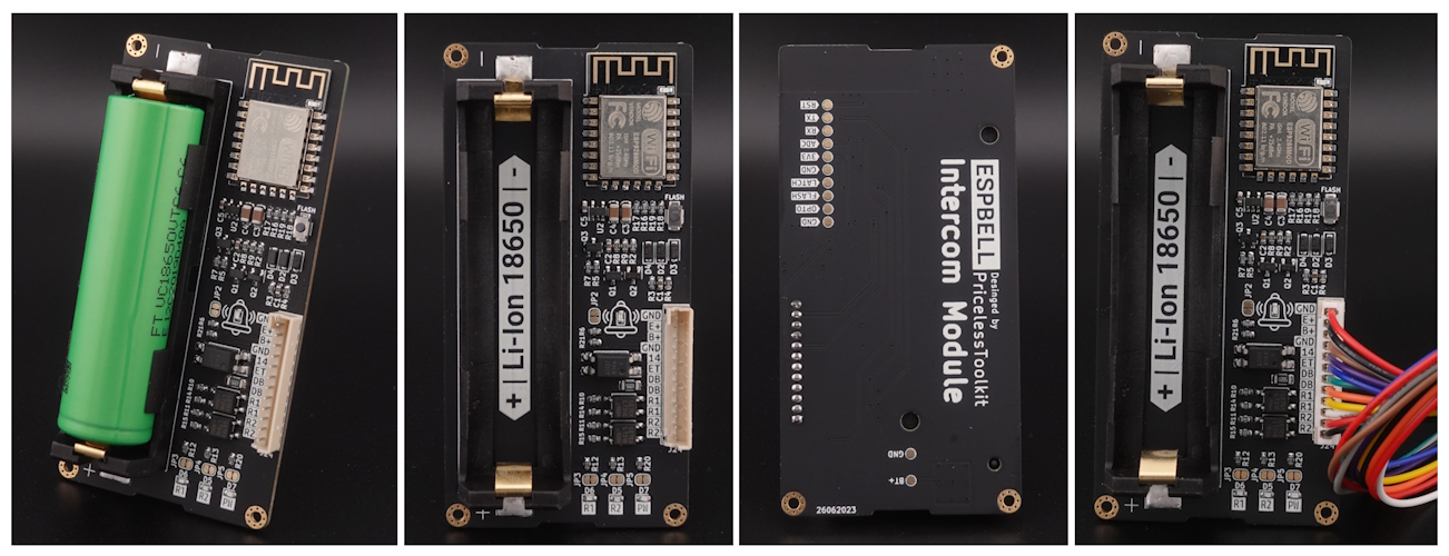
ESPBell-MAX and ESPBell-LITE
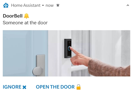
ESPBell-MAX "IoT Intercom / Doorbell" module enables you to stay informed whenever someone rings your doorbell or presses the intercom button. Upon receiving an interactive notification, you have the convenience to either promptly open the door or choose to dismiss the alert by simply tapping the button within the notification. See the screenshot below.
Notification Screenshot
Supported software and future plans
Currently supported Home Assistant and MQTT If I have time I'll add control by Telegram and WhatsApp
Contributors
Note
If you're ready to contribute to the project, your support would be greatly appreciated. Due to time constraints, I may not be able to quickly verify new "features" or completely new "code" functionality. Therefore, please refrain from making changes to the original code. Instead, create a new code/script in the 'Contributors_code' folder and use this README_Contributors.md Thank you very much!
Links
- YouTube video How To
- My Shop
- Aliexpress
- Pogo pin Clamp Fixture
- Battery
- Charger
- Vis and Insert "Optional for 3D Case"
- 3 x Vis M2 4mm - https://s.click.aliexpress.com/e/_DFzWgSp
- 3 x Insert M2(OD 3.2mm) - https://s.click.aliexpress.com/e/_DkM0Kfb
Specifications
- Based on ESP12F "Programmable via pads on the PCB"
- Power consumption
- Standby mode: 0.08mA "Per Mont!"
- When triggered: 21uA/s
- Input / Output
- 2 x "R1/R2" SSR 2.4A 30v Max
- 1 x "DB" Input Optocoupler 2-30v AC/DC Max "For Doorbell"
- 1 x "ET" Input 3.3-5v DC Max "External Trigger"
- 1 x "B+" Battery Voltage "Permanent output"
- 1 x "E+" Battery Voltage "When ESPBell is enabled"
- 1 x "GPIO14" 3.3v DC MAX
- 2 x GND "Only! for ET/B+/E+/GPIO14"
- Status LEDs - Can be deactivated "PCB Jumper"
- 1 x R1
- 1 x R2
- 1 x DoorBell
- 1x Power
- 1x On ESP module "Not used"
- Battery type Li-Ion 18650
- Button for flashing Firmware
Before you start
Note
✅ Please check your Intercom type. It needs to be a 5-wire intercom system. I hope that everything is crystal clear as I've made every effort to provide a step-by-step explanation of the setup process. If you have any further questions regarding the setup or require assistance with assembling a printed circuit board, feel free to join our Facebook Group or open a new discussion topic in the dedicated tab.
Important
If you're new to Arduino-related matters, please refrain from asking basic questions like "how to install Arduino IDE". There are already plenty of excellent tutorials available on the internet. If you encounter any issues, remember that providing detailed information about the problem will help me offer more effective assistance. More information equals better help!
Warning
I would strongly advise against attempting to assemble this PCB on your own if you have no experience "0%" in soldering, or working with ESP / Arduino boards. Connecting ESPBell-MAX to your intercom or doorbell demands a certain level of electronics expertise and the proficiency to utilize a multimeter effectively. Please be aware that I cannot assume responsibility for any errors or issues that may arise. My role is to provide guidance and advice to the best of my abilities.
PCB Assembly
This project is open-source, allowing you to assemble ESPBell-MAX on your own. To simplify this process, I've provided an "Interactive HTML Boom File" located in the PCB folder. This interactive file helps you identify where to solder each component and polarity, reducing the chances of errors to a minimum. But if you don't feel confident in assembling it yourself, you can always opt to purchase a pre-assembled board from my Shop
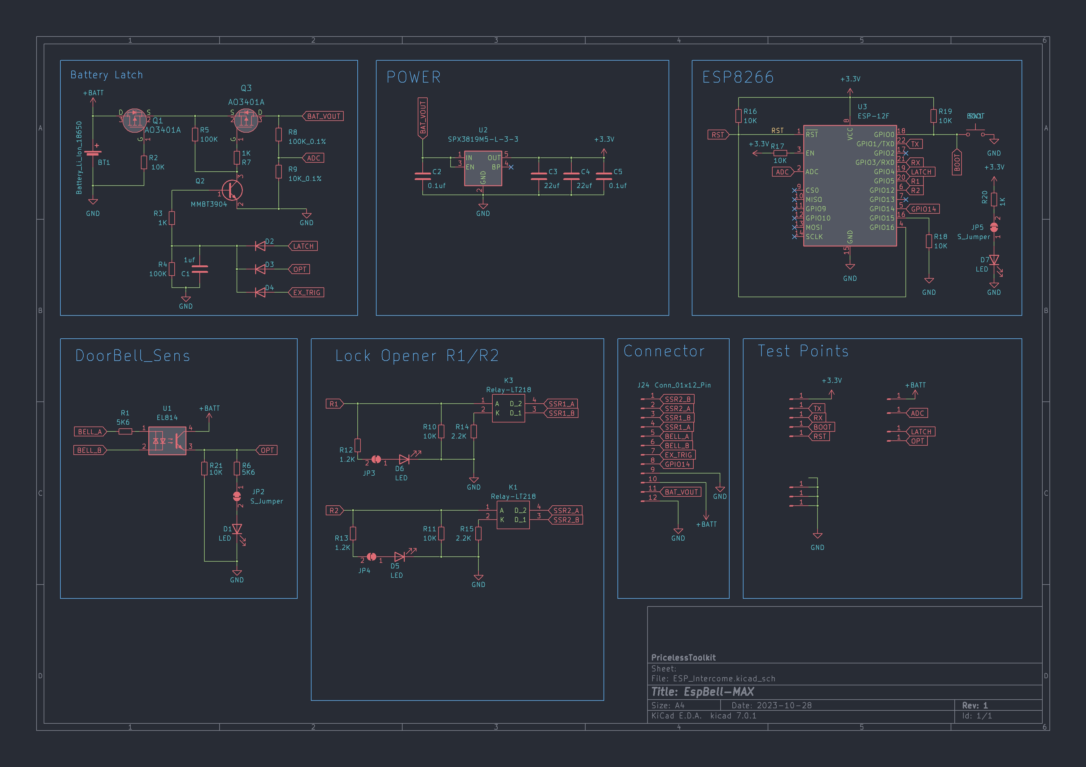
Schematic
View schematic. Click here
Arduino IDE Configuration
Used Arduino Libraries
#include "ESP8266WiFi.h"
#include <PubSubClient.h>
If you are using ESP8266 for the first time, you need To install the ESP8266 board and PubSubClient library in your Arduino IDE.
- In your Arduino IDE, go to File> Preferences.
- Enter
http://arduino.esp8266.com/stable/package_esp8266com_index.jsoninto the “Additional Boards Manager URLs” field. Then, click the “OK” button - Open the Boards Manager. Go to Tools > Board > Boards Manager.
- Search for ESP8266 and press the install button for the “ESP8266 by ESP8266 Community“
- Search for PubSubClient and press the install button.
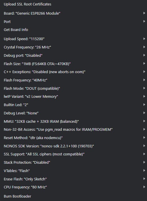
For board configuration in IDE, see the screenshot below
Board config Screenshot
ESPBell-MAX MQTT sketch configuration
Note
For ESPBell-MAX_MQTT_Auto_Discovery.ino
all configurations are done in the file config.h
WI-FI Settings
To ensure a rapid Wi-Fi connection, we skip the Wi-Fi scanning process. Instead, we simply provide the access point's name, channel, and MAC address. This efficient method significantly shortens the connection time to the access point, taking just about 300 milliseconds.
Important
Make sure to set a fixed channel on your Wi-Fi access point.
#define WIFI_SSID "Your_WIFI_SSID"
#define WIFI_AUTH "Your_WIFI_Password"
#define DATA_WIFI_CH 6 // Put your Wi-Fi channel and disable channel hopping in your WI-FI Access Point
#define DATA_WIFI_BSSID {0xAA, 0xAA, 0xAA, 0xAA, 0xAA, 0xAA} // Change only AA part.
Local Network Settings
As the DHCP-based IP address assignment may introduce certain delays, we can optimize the process by manually assigning and registering the IP address.
Important
Use IP address outside of DHCP Range.
// IP address, network mask, Gateway, DNS
#define DATA_IPADDR IPAddress(192,168,99,2) // Use IP address outside of DHCP Range
#define DATA_IPMASK IPAddress(255,255,255,0)
#define DATA_GATEWY IPAddress(192,168,99,1)
#define DATA_DNS1   IPAddress(192,168,99,1)
MQTT Settings
Fill in Mosquitto broker credentials and IP address.
const char* mqtt_username = "Your_MQTT_Username";
const char* mqtt_password = "Your_MQTT_Password";
const char* mqtt_server = "MQTT/HomeAssistant_IP";
const int mqtt_port = 1883;
Timing Settings
Optimal performance and energy efficiency hinge upon these configurations, consisting of three critical parameters. It's important to note that 1000ms equates to 1 second.
Explanation click here
upTime: This variable represents the time delay, in milliseconds, before initiating a 'Power Off' operation by setting the Latch PIN to LOW. You can adjust this value to determine how long the system should wait after waking up before powering down.openTime: This variable sets the duration, in milliseconds, during which the relays remain active. Modify this value to control how long the relays stay on.
autoOff: This parameter can be set to either 0 or 1:
- 0: DISABLED - ESPBell will power down after the 'upTime' specified.
- 1: ENABLED - ESPBell will automatically power down after the 'openTime' has elapsed.
Important
When using ESPBell-MAX with an intercom system select your 'upTime' value carefully to ensure you have sufficient time for picking up your phone, checking notifications, and pressing the action button, along with a little extra time in reserve for added convenience. In the doorbell setup 2s 'upTime' is more than enough.
// 1000 = 1s"
const long upTime = 15000;  // How long to wait after wakeup before powering off "Latch PIN to LOW"
const long openTime = 2000;  // How long relays is on.
const int autoOff = 1; // 0 = DISABLE / 1 = ENABLE // Powering off automatically after "openTime" // if is set to 0 ESPBell will power down after upTime.
Uploading the Arduino sketch
To upload the sketch into ESPBell-MAX you will need two things.
- Regular USB-TTL 3.3v adapter. I have open-source USB-TTL project, in case you don’t have a TTL adapter yet and want to assemble it yourself.
- Pogo pin Clamp Fixture "single row 6 Pin 2.54mm spacing" or you can solder wires directly to ESPBell-MAX for programming.
USB-TTL Wiring diagram
| USB-TTL | ESPBell-MAX |
|---|---|
| TX | RX |
| RX | TX |
| GND | GND |
| 3.3v | 3.3V |
You need to put the ESPBell-MAX into download mode to upload the firmware, for that, press and hold the Flash button on the ESPBell-MAX, then plug in the USB and press the upload button in Arduino IDE, Don't release the Flash button until you see the upload progress.
Home Assistant Configuration
Note
After connection, Home Assistant will automatically discover ESPBell-MAX with 3 sensors.
- Bell | Statuses is OPEN / CLOSE
- RSSI | in dBm
- Battery | in percent 0-100% "3.2-4.2V" Because the ESP8266 ADC is inaccurate, measurements can fluctuate.
Here is a multi-user configuration example, which means that a notification is sent to several family members. If one family member clicks on the notification, the notification disappears from the other phones. For all this to work we need to create "three" automation, but before that, in this example, you need to change a minimum few things.
- Image file path that is used as a background for Notification.
- The name of the mobile device that is connected to the Home Assistant. In my case, it's "doogee_v20pro" and "Second_Phone"
  image: /media/local/notify/doorbell.jpg
- service: notify.mobile_app_doogee_v20pro
- service: notify.mobile_app_Second_Phone
Automation 1
This automation sends an interactive notification with the "tag: intercom" to phones.
Explanation click here
Alias: This is a user-defined name or label for the automation. In this case, it's given the name "🔔 Intercom DoorBell Notification," which suggests that it's related to receiving notifications for an intercom or doorbell event.Description: This field is left empty, so there's no additional description provided for this automation.
Trigger: The trigger specifies the event or condition that will start the automation. In this case, it is triggered when the state of the "binary_sensor.espbell_max_bell" changes to "on." This implies that the automation will run when the binary sensor named "espbell_max_bell" switches from an off state to an on state.
Condition: There are no additional conditions specified. This means the automation will proceed without any additional conditions beyond the trigger.
Action: The action section defines what should happen when the trigger condition is met. In this case, there are two actions defined:
The first action uses the "notify.mobile_app_doogee_v20pro" service to send a notification to a mobile device. The notification includes a message "Someone at the door" and is configured with various data attributes, including a persistent notification, high importance, a specified channel ("intercom"), and a tag ("intercom"). It also includes an image file path for the notification and two actions that can be taken by the recipient: "Ignore ✖" and "Open The Door 🔓." The title and message of the notification are also specified in two languages (English and French).
The second action is similar to the first but uses the "notify.mobile_app_Second_Phone" service to send the same notification to another mobile device.
Mode: The mode is set to "single," which means that the automation will only run once for each trigger event. Subsequent trigger events will not cause the automation to run again until the current execution has been completed.
alias: 🔔 Intercom DoorBell Notification
description: ""
trigger:
  - platform: state
    entity_id:
      - binary_sensor.espbell_max_bell
    to: "on"
condition: []
action:
  - service: notify.mobile_app_doogee_v20pro
    data:
      message: Someone at the door
      data:
        persistent: true
        importance: high
        channel: intercom
        tag: intercom
        image: /media/local/notify/doorbell.jpg
        actions:
          - action: intercom_ignore
            title: Ignore ✖
          - action: intercom_open
            title: Open The Door 🔓
      title: DoorBell 🔔
      message: Quelqu'un à la porte
  - service: notify.mobile_app_Second_Phone
    data:
      message: Someone at the door
      data:
        persistent: true
        importance: high
        channel: intercom
        tag: intercom
        image: /media/local/notify/doorbell.jpg
        actions:
          - action: intercom_ignore
            title: Ignore ✖
          - action: intercom_open
            title: Open The Door 🔓
      title: DoorBell 🔔
      message: Quelqu'un à la porte
mode: single
Automation 2
This automation clears notifications with the "tag: intercom" on phones when an ignore button on the notification is pressed.
Explanation click here
Alias: The alias is a user-defined name or label for the automation, and in this case, it's named "🔔 Intercom DoorBell ignore notification Dismiss." This name suggests that the automation is related to dismissing or ignoring notifications for an intercom or doorbell event.Description: The description field is left empty, so there's no additional description provided for this automation.
Trigger: This automation is triggered by an event. The trigger condition is defined as follows:
platform: The trigger platform is "event," which means the automation will be triggered by an event.
event_data: The automation will only trigger when the event data contains a specific action. In this case, the trigger event is looking for events with the action "intercom_ignore."
event_type: The automation is tied to the "mobile_app_notification_action" event type. It implies that this automation is designed to respond to actions taken by the user within a mobile app notification.
Condition: There are no additional conditions specified. This means the automation will proceed without any additional conditions beyond the trigger.
Action: The action section specifies what should happen when the trigger condition is met. This automation has two actions:
The first action uses the "notify.mobile_app_doogee_v20pro" service to send a notification with the message "clear_notification." It also includes data attributes with the "tag" set to "intercom." This effectively clears or dismisses the notification with the "intercom" tag on the "mobile_app_doogee_v20pro" mobile app.
The second action is identical to the first but uses the "notify.mobile_app_Second_Phone" service to clear or dismiss the notification on another mobile device with the "intercom" tag.
Mode: The mode is set to "single," which means that the automation will only run once for each trigger event. Subsequent trigger events with the "intercom_ignore" action will trigger this automation, but it will only clear the notification once.
alias: 🔔 Intercom DoorBell ignore notification Dismiss
description: ""
trigger:
  - platform: event
    event_data:
      action: intercom_ignore
    event_type: mobile_app_notification_action
condition: []
action:
  - service: notify.mobile_app_doogee_v20pro
    data:
      message: clear_notification
      data:
        tag: intercom
  - service: notify.mobile_app_Second_Phone
    data:
      message: clear_notification
      data:
        tag: intercom
mode: single
Automation 3
This automatization enables the Relays R1/R2 by publishing the MQTT payload and clears notifications with the "tag: intercom" on phones when the notification button is pressed on one of the phones. Solid-state relays are controlled by publishing the MQTT payload. MQTT Command Topic is "homeassistant/sensor/espbell-max/command" Payload is "00" The first digit is controlling R1 second digit R2.
- "01" R1=OFF R2=ON
- "11" R1=ON R2=ON
- "10" R1=ON R2=OFF
- "00" R1=OFF R2=OFF
alias: 🔔 Intercom open the door and Dismiss notification
description: ""
trigger:
  - platform: event
    event_data:
      action: intercom_open
    event_type: mobile_app_notification_action
condition: []
action:
  - service: mqtt.publish
    data:
      qos: 0
      retain: false
      topic: homeassistant/sensor/espbell-max/command
      payload: "10"
  - service: notify.mobile_app_doogee_v20pro
    data:
      message: clear_notification
      data:
        tag: intercom
  - service: notify.mobile_app_Second_Phone
    data:
      message: clear_notification
      data:
        tag: intercom
mode: single
Wiring diagram ESPBell-Max to Intercom | Doorbell
Intercom
Differences Between 4+N and 1+N Intercom Systems. Click here
In the world of intercom systems, two common configurations stand out: 4+N and 1+N. Understanding the distinctions between these setups is crucial for successful installation and operation. Here's a quick overview:
4+N Intercom Systems:
In a 4+N system, the "4" signifies the presence of four distinct wires, each with a specific purpose. These four wires are typically allocated as follows: one for the microphone, one for the speaker, one for the doorbell, and one for the lock. Additionally, the "N" wire represents the neutral wire, which is used for the electrical current's return path. 4+N systems offer separate wiring and control for microphone, speaker, doorbell, and lock functions.
1+N Intercom Systems:
In contrast, a 1+N system streamlines the wiring process by combining audio communication and power supply over a single wire. The "1" in 1+N indicates that one wire is used for both audio communication and power transmission. Like 4+N systems, the "N" wire in 1+N systems also stands for the neutral wire. 1+N systems simplify wiring, using a single wire for audio and power, making installation more straightforward.
4+N Intercom System wiring diagram. Click here
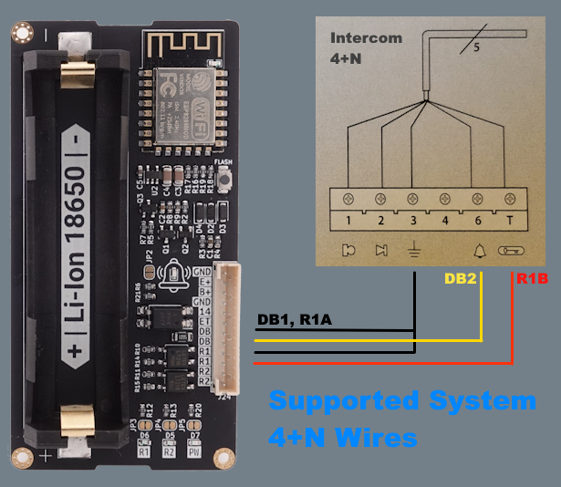
Note
Currently, only the 4+N Intercom system is supported by ESPBell-MAX. But if you want you can connect ESPBell-MAX to the unsupported intercom buttons directly!
Doorbell
Dorbell wiring diagram. Click here
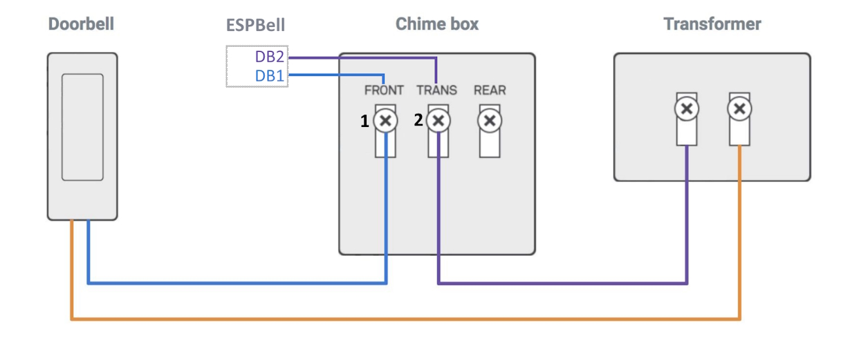
Warning
If there is current leakage between contacts 1 and 2 see "Dorbell wiring diagram" ESPBell may trigger randomly "The current flow may be due to the installed light bulb in the doorbell button which illuminates all the time" So before you start it’s better to check it with a multimeter.