This repository contains code to run PINT in the Tofino ASIC.
The repository only includes the data plane part of PINT for Tofino, and does not explain how to process the generated telemetry data at the controller.
This project requires an installed and set up Tofino switch.
During development, a Stordis BF2556X-1T was used with SDE version 8.9.2.
A single switch is used to emulate multiple switching running PINT.
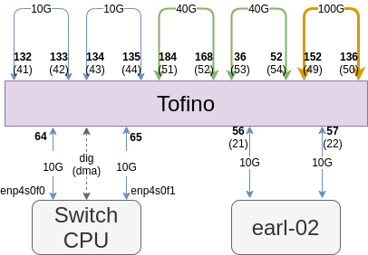
This is achieved through external loopback, requiring cabling according to the link configuration section
- Compile the PINT code
- Start the PINT program on the Tofino
- Configure the Tofino ports, which in our case are these rules
- Start the switch CPU component using start_switch_cpu.sh
- Inject packets from the switch CPU using pktgen.py
The injected packets will be processed by PINT, and the controller should print the raw generated output
During development, our Tofino had links connected according to the following image:
This is the topology used during development of PINT on the Tofino:
Traffic is sent by pktgen.py from h0(10.0.0.101) towards h1(10.0.0.102), with each switch running the pint.p4 pipeline.
The last hop, i.e. the PINT sink, will send the telemetry data down to the switch CPU

