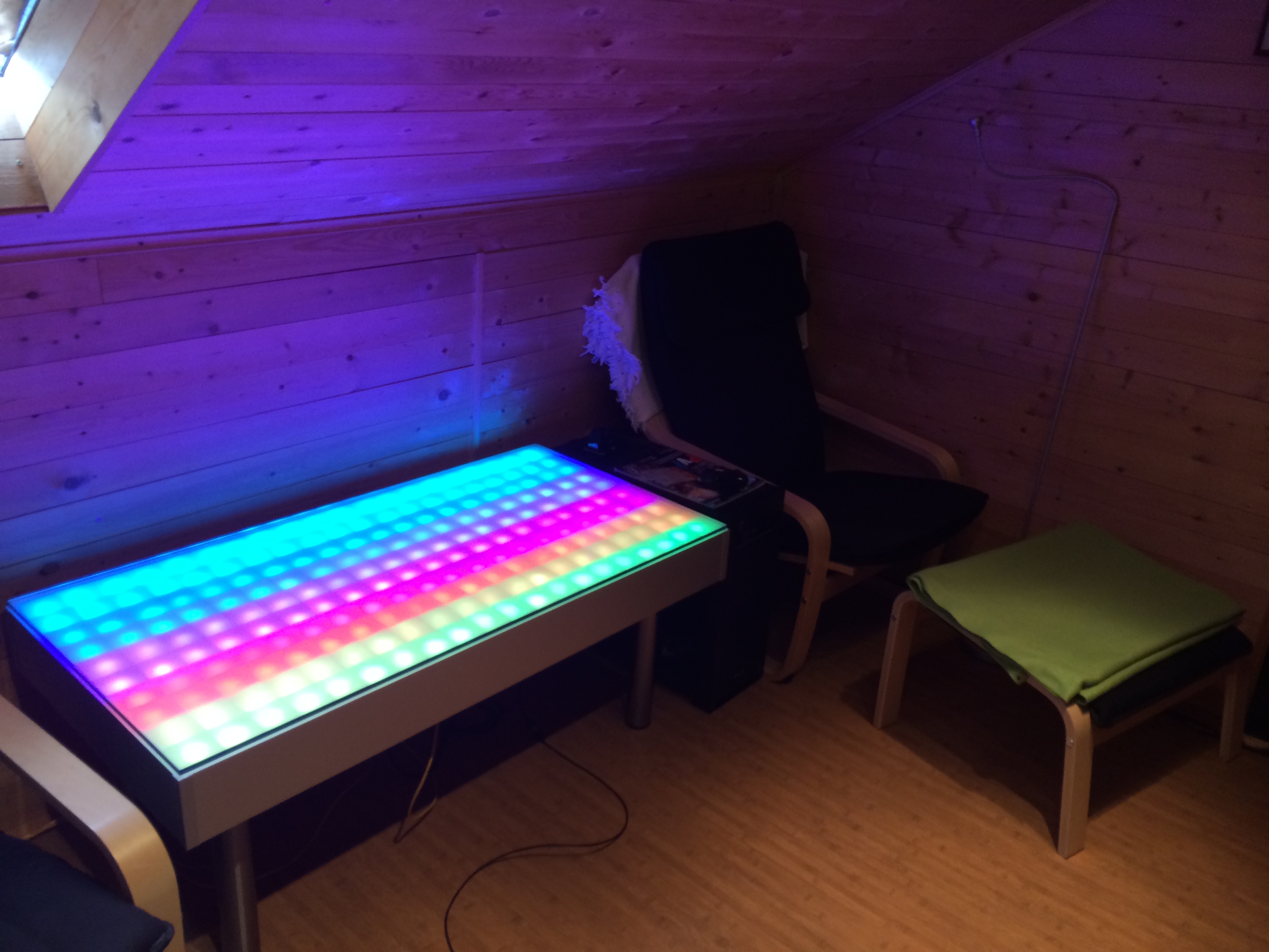
A RGB-Table with 200 pixels, NES Controller support, Webinterface.
- Tablesize 120x60cm
- 10x20 RGB WS2812 LED MATRIX (6x6xm Pixelsize)
- Webinterface for control
- RTC
- NES Controller Support for Games
- Arduino DUE
- Massive construction so you can jump on
- API
- NIGHTMODE (switch on/off at specific times)
Each mode have several options to customise the color, speed,...
- RAINBOW
- CONSTANT COLOR
- RANDOM COLOR / PIXELS
- CLOCK
- SCROLLING TEXT (with numbers and special characters)
- RSS Display (required a RaspberryPi on SerialPort1 of the Ardino)
- TableInformationSystem (T.I.S) for display text/data from USB
- SNAKE
- 2048
- PAINT
- SENSO
- PONG
- 1 Arduino DUE
- 1 Arduino Ethernet Shield
- 1 RTC Module (DS3231 or DS1307)
- 200 WS2812 5mm RGB LEDs
- 2 NES Controller jack
- 5V 10A switching power supply
- 5V Fan
- 2 Relais
- 1 PCB Pushbutton
- 2 4 channel levelshifter (5V -> 3.3V)
- tons of wires for the leds (but you can buy pre wired leds, DO IT)
- luster terminals
- pcb board
- 1 120x60x10mm plywood ground plate (
GROUND_PLATE) - 1 120x60x3mm poplar wood plate for the leds (
LED_PLATE) - 1 120x60x8mm glass plate
- 1 120x60x3mm acrylic glass plate with 75% transparency
- plastic L profiles
- plastic I profiles
- 10x10mm [] wood profiles
- 30x5mm I wood profiles
- 4 table legs (height depend on your needs)
- alumninium plates for coverage the wood
- Drill 5mm, 8mm, 10mm
- Hotglue-Gun
- Soldering equipment
- Saw
- woodglue
- (torks) wood screws 20mm, 30mm
- tons of zipties
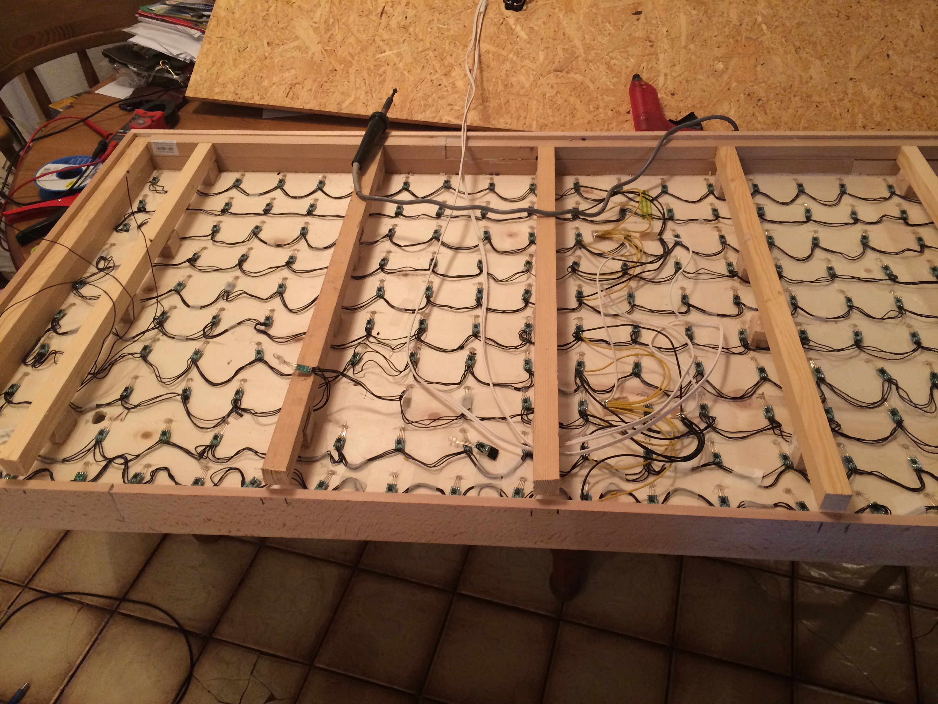
- drill 200 holes with the 5mm drill into the
LED_PLATEwith 60mm distance to each other, to get the led matrix - glue each of the 200 (connected led = one strip,
DOUT -> DIN), into one hole of theLED_PLATE, fix it with hotglue - mount pieces of the 10x10mm [] wood profiles unter the
LED_PLATEfor spacing - drill holes into the
GROUND_PLATEfor the led wires - glue and screw the
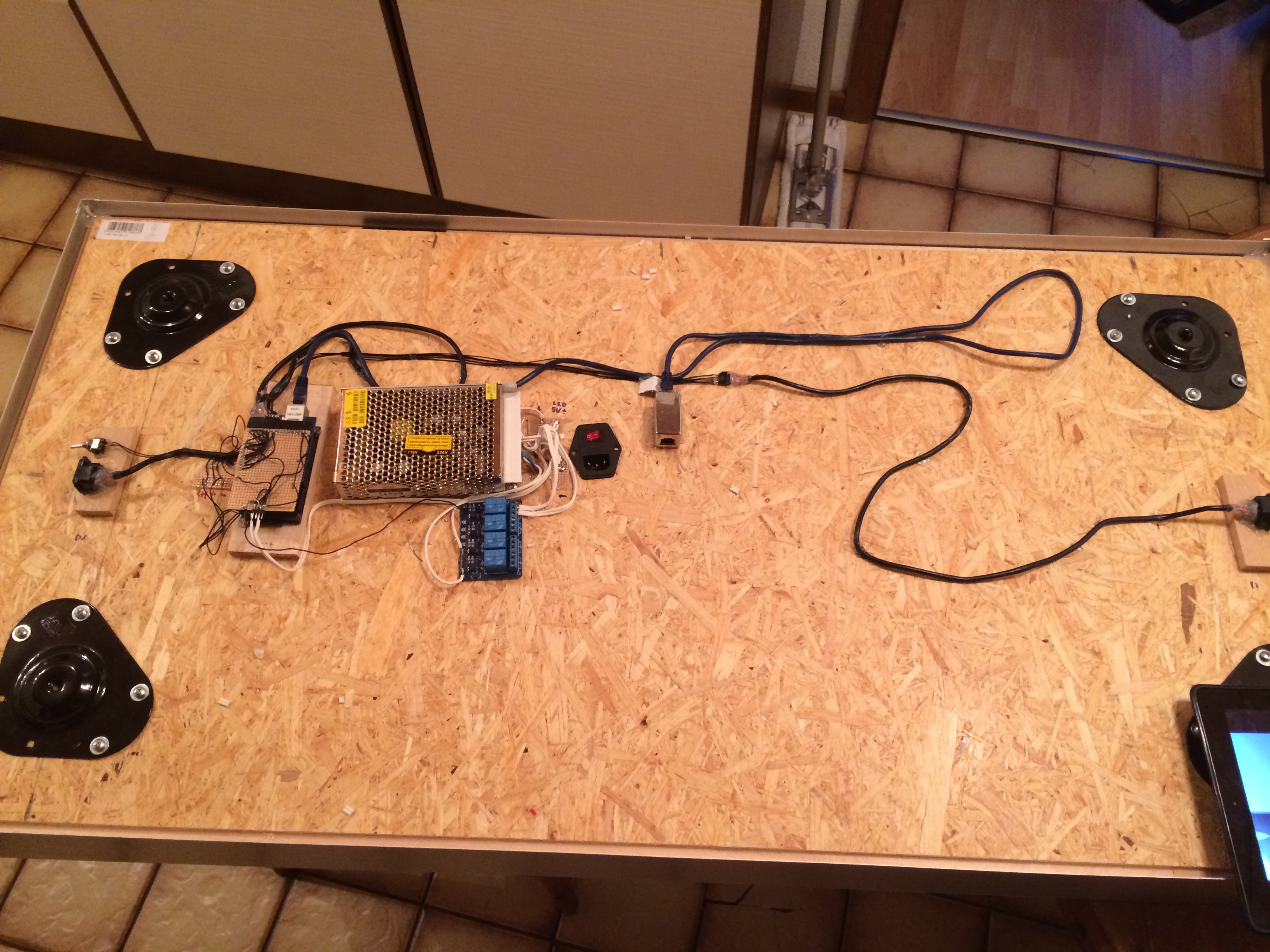
LED_PLATEwith the spacers on to theGROUND_PLATE - mount the table leg plates on each corner of the
GROUND_PLATE - mount the power supply and the arduino (with rtc connected, relais, switch, nes controllers) under the
GROUND_PLATE - connect relais channel 1 beween power supply and
VCCof the leds - connect relais channel 2 beween power supply and
VCCof the fan - connect the first led
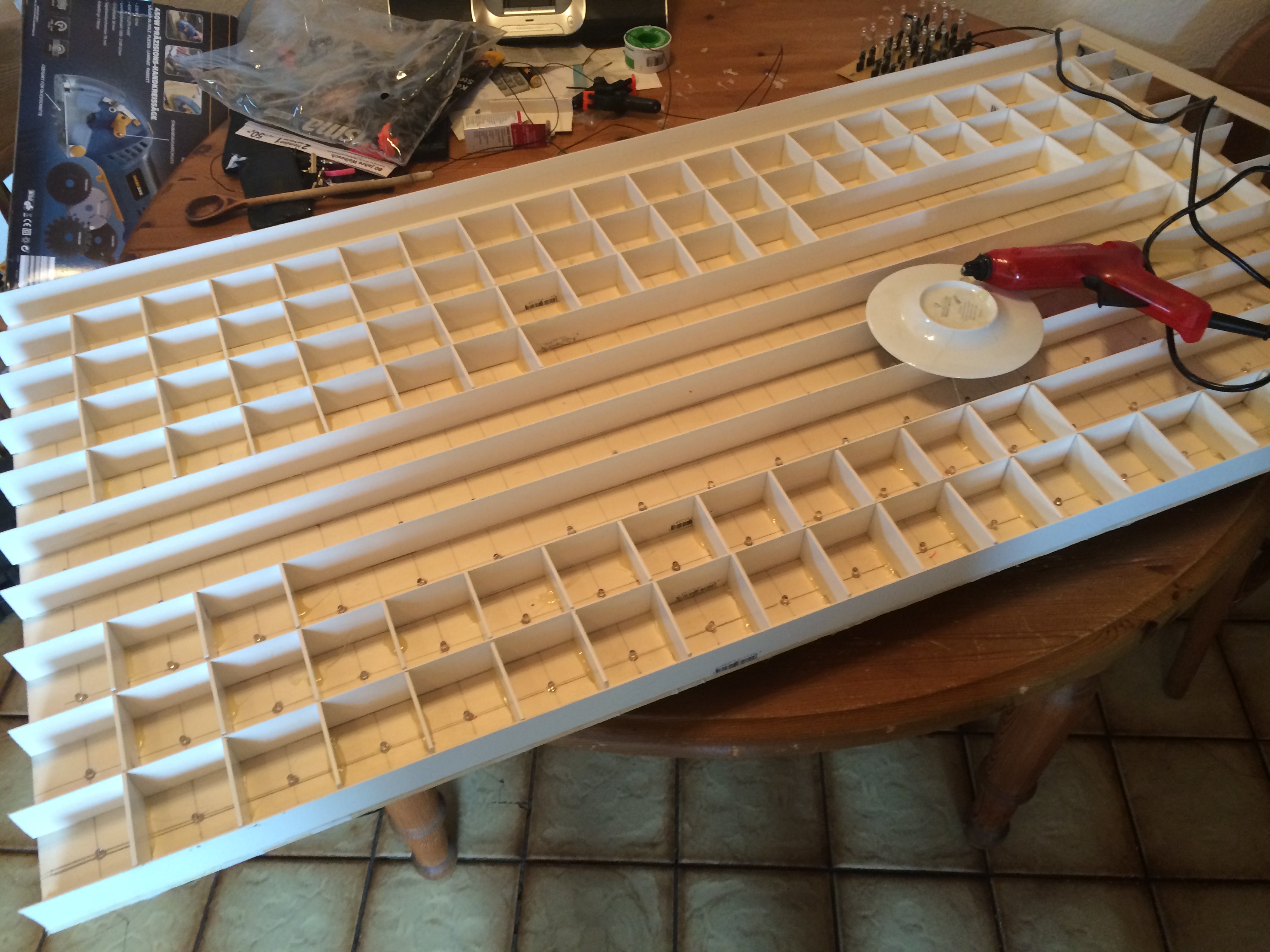
DINthrough the levelshifter to the arduino - place the L and I prfiles on top of the
LED Plateso that it gives a matrix (see pictures) - place the I 30x5mm wood profiles around the
GROUND_PLATE/LED_PLATEto build the frame and glue/screw it - mount/screw the table legs
- place the acrylic glass plate over the matrix
- place the glassplate over the matrix
- cover frame around the table with alumninium plate
For a long version, send me a message
- download the latest Arduino IDE
- download the webserver libary : https://github.com/sirleech/Webduino
- download the flash-storage libary : https://github.com/sebnil/DueFlashStorage
- download the latest sketch from this repo, located at /ARDUINO CODE/table_due_beta35_Websitetitel.txt
- set the pin config (line 9 - 16)
- flash the sketch to your arduino
- connect a ethernet cable
- power it on
- the ip is shown at powering up
- connect to the ip of the table
- look at the settings section for timezone and other settings
- HAVE FUN
At the first power on you must hold the pushbutton, to write the default config


