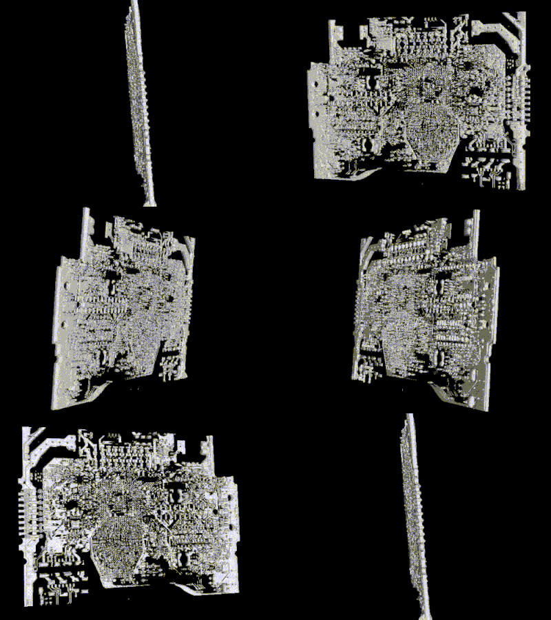
This repository describes the way we get non-invasive arbitrary code execution on the Siemens S7 PLC by using an undocumented bootloader protocol over UART. Siemens assigned SSA-686531 (CVE-2019-13945) for this vulnerability. Affected devices are Siemens S7-1200 (all variants including SIPLUS) and S7-200 Smart. The list of the content are as follows:
In this section we will provide quick overview about the device.
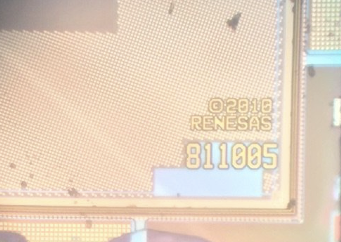
We used an S71200, CPU 1212C DC/DC/DC 6ES7 212-1AE40-0XB0 for our research. The SoC in the our device was an A5E30235063 relabelled as Siemens SoC. However, the SoC decapsulation reveals that the SoC is based on Renesas 811005 (model 2010) as illustrated in the figure below:
The exact version of the ARM instruction set running on the PLC was queried using the following ARM instruction:
mrc p15, 0, r0, c0, c0, 0We got a response with value 0x411fc143 (0b1000001000111111100000101000011), meaning that it is a ARM Cortex R4 Revision 3, ARMv7 R, Thumb 2 Real-Time profile SoC with Protected Memory System Architecture (PMSA), based on a Memory Protection Unit (MPU).
The S7-1200 DC/DC/DC v2018 is using Micron Technologies NQ281 (FBGA code) 1Gbit (128MB) flash. Using Micron FBGA decoder we could get the part number of the flash. The part number is MT29F1G16ABBDAHC-IT:D. Note that in mid 2019, Siemens updated the NAND Flash to NW812 (MT29F1G08ABBFAH4-ITE:F).
Siemens S7-1212C v4 is using a 1GB Winbond W94AD2KB or 256MB W948D2FBJX6E high-speed LPDDR1 SDRAM or a Micron Technologies MT46H32M32LFB5-5 IT (FBGA code D9LRB) in a 90-Ball VFBGA form. The RAM is running at 100Mhz.
An interesting observation we made when looking at the firmware more deeply to investigate non-invasive access techniques is a protocol over UART during the very early boot stage implemented by the bootloader (v4.2.1). During startup, the bootloader waits for half a second, listening on the serial input to receive a magic sequence of bytes. Upon receiving those bytes in the given timeframe the bootloader enters a special protocol offering a large variety of functionality over serial. A client for the UART protocol containing functionality to execute payloads on the PLC from within early boot is implemented in this utility.
In the bootloader at address 0x0368 is called to wait for a magic string "MFGT1" within half a second. If such a string is encountered, it will answer with the string "-CPU" and return 1 to indicate that the protocol handler is getting executed. The return value of this function is checked at 0x0EDF0 and the protocol handler at 0xF3D0 is entered if the initial handshake has been performed.
The UART protocol handler exposes a list of low level functions. There are multiple layers of handlers present in the system:
- Primary Handlers: A primary list of handlers that can be invoked directly from the first protocol stage. They are stored in a table inside the bootloader starting at address
0x014D98with 128 entries. - Additional Hooks: The first stage handler residing at address
0x00011180with the assigned handler index0x1callows calling hooks from a second list starting at0x00015280. - Subprotocol: A Primary Handler 0x80 at
0x0000D1F0(handler index0x80) enters an additional menu loop exposing what seems to be a setup/read/write triple of operations for different kinds of devices/components in the system such as flash, IRAM and an unknown device type.
Whenever contents are sent by one party, the following structure is expected by the protocol:
<length_byte><contents><checksum_byte>
The length is a single byte value field describing the length of contents+1. The checksum is a byte that completes the sum of all input bytes (including the length byte) to 0 mod 0x100.
The Primary Handler function is located at 0x0000EE48. Commands are accepted in the form of single packets/messages as described above. After a correctly checksum packet is received, the first byte of the packet is interpreted as the command number.
For command number 0x80, the Subprotocol handler is invoked in a mode based on the next two bytes of the incoming message (0x3BC2: mode 1, 0x9D26: mode 2, 0xE17A: mode 3, 0xC54F: mode 4).
Command number 0xA2 represents the exit command. Command 0xA0 allows some configuration of the UART protocol. The semantics are not yet exactly determined.
For command numbers lower or equal 0xB0, the respective Primary Hook inside the handler table starting at 0x00014D98 is invoked.
A second layer of handlers is accessible via the first stage handler residing at address 0x00011180 with the assigned handler index 0x1c. It relays invocations to a second layer of functions based on the arguments provided inside the packets sent by the other side of the protocol. The list of this secondary handler is initially stored in a table starting at 0x00015280 inside the bootloader. Before actual usage the table is then copied over to 0x1003ABA0 and then the copy in RAM is accessed rather than contents in the bootloader. This is important as overriding the actually used function pointers does not involve modifying bootloader memory (which may expected to be read-only and may trigger detection mechanisms and failing checksum tests).
The table containing the additional hooks has 33 entries. The index of this hook is checked against the boundaries 0<=index<=32. Also, each table entry contains information about the length of the input expected by the particular additional hook:
0: The handler is disabled1-0xfe: The input length has to match the given value exactly0xff: Variable input length
A list of the Additional hooks can be retrieved from the list inside the bootloader starting at 0x15280 . The reversing maturity of those handlers is not very advanced so a list is not generated here. Looking at the actual functions should be the best option to understand the range of functionality should the need arise. By default most handlers are disabled from being executed directly.
This handler seems to be responsible for performing updates of different components over UART. To enter this protocol in one of four modes, handler 0x80 has to be invoked with a 2-byte argument describing the mode used by the sub handler. Every mode corresponds to one component to be updated:
| Mode Number | Component |
|---|---|
| 1 | Hardware device mapped to memory around region 0x10000000. This seems to match IRAM memory |
| 2 | SPI1 / IOC mappings are used here, exact component so far unknown |
| 3 | Firmware flash memory |
| 4 | NOP |
For each component, three to four types of functions are supported. The rough semantics are: Preparation/Setup, (Metadata) Read, (Update) Write, Cleanup.
When the subprotocol handler is entered, another loop handling commands sent via UART is performed. At least one argument byte is expected from here which - together with the overall input length - acts as a switch for the function to be used.
The handler that is the most important for getting code execution is handler number 1 (writes internal memory such as ITCM and IRAM). A way to update flash contents is sub-handler number 3.
Using a combination of the functionality provided above we were able to gain arbitrary code execution on the device using the UART protocol. The client implementing this is located at client.py.
The idea behind the implementation is as follows:
- Use the subprotocol handler's memory RAM update component to inject a custom shellcode payload to IRAM. This is implemented as the first step in the function
_exploit_install_add_hookin client.py - Use the subprotocol handler's memory RAM update component to create a function pointer to the custom shellcode above by injecting an additional hook address into the additional hook table in IRAM at
0x1003ABA0. This is implemented as the second step in the function_exploit_install_add_hookin client.py - Use the handler
0x1cto call the custom shellcode. This is implemented in the functioninvoke_add_hookin client.py
We spotted similar functionality in 2014 models of S7-1212C Siemens PLCs (6ES7212-1BE31-0XB0). The bootloader functionality was spotted at offset 0xE664 of older PLC bootloader (S7-1200v3).
As mentioned earlier we used a 6ES7 212-1AE40-0XB0 S7-1200 PLC with a ALLNET ALL3075V3 Network controlled socket and a FTDI FT232RL USB to TTL Serial Converter.
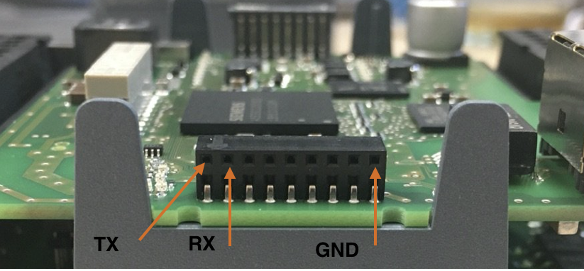
To be able to utilize this utility you need to connect to a UART interface of the PLC. For the pins on the side of the PLC (next to the RUN/STOP LEDs), populate the top row like the following:
One can use any TTL 3.3V device. Obviously you should connect TX pin of the TTL adapter to the RX port of the PLC and RX port of the TTL adapter to the TX port of the PLC.
Once you copied our repo go to uart_rce folder. You also need to get the name of your TTYUSB adapter in /dev folder of your linux machine. Generally it will be /dev/TTYUSB0 (This name is hardcoded in start.sh). You also need to install required python libraries and arm-none-eabi compiler to compile payload for the PLC. Additionally, you must set the IP address of ALLNET ALL3075V3 to 192.168.0.100 (you can change this value inside client.sh script).
To actually compile the payload go to uart_rce/payloads folder. There are various payloads available. Each payload have a build.sh file. To compile them you can go inside the folder and run the build bash file. For example, here we compile the hello_world payload which is used for our test mode :
research@ali-Plex-9:~/SiemensS7-Bootloader/uart_rce/payloads/hello_world/$ sh build.shOnce we are done compiling the payloads for Cortex-R4 CPU, we can open the channel for forwarding our UART serial data to a TCP port which will be used by our client utility. This console window should show you raw UART traffic between PLC and client utility:
research@ali-Plex-9:~/SiemensS7-Bootloader/uart_rce$ sh start.shNow, we can use our client utility. Open a new console window (without closing the console which runs start.sh), and type the following command for uploading the stager and test payload to the UART:
research@ali-Plex-9:~/SiemensS7-Bootloader/uart_rce$ sh client.sh --switch-power --powersupply-delay=1 testThe --powersupply-delay is provided for Cold-boot style firmware dumping (we do not use it at this stage but providing this item is required). The argument test uses the payload in payloads/hello_world/hello_world.bin file. This payload literraly just run inside the PLC and send string TEST back to the client, thus client knows the code successfully executed inside the PLC.
In this demo we decided to upload the Tic-tac-toe game to the PLC. The goal of this demo is to demonstrate running more complex form of programs inside the PLC. To upload the game, you need to first compile it:
research@ali-Plex-9:~/SiemensS7-Bootloader/uart_rce/payloads/tic_tac_toe$ make
cc tic_tac_toe.c
cc ../lib/stdlib.c
cc ../lib/print.c
cc ../lib/string.c
cc ../lib/read.c
ld tic_tac_toe.sym
strip tic_tac_toe
objcopy tic_tac_toe.ihex
objcopy tic_tac_toe.bin
Now we must use the tictactoe mode of our script utility as it allows us to interact with the PLC and have stream of input/output:
research@ali-Plex-9:~/SiemensS7-Bootloader/uart_rce$ sh client.sh --switch-power --powersupply-delay=1 tictactoe --payload=payloads/tictactoe/build/tictactoe.binNote that the tictactoe mode, allow us to use alternative payloads using --payload argument. So we are not bounded to only use the tictactoe.bin payload.
We have alternate version of hello_world which the PLC instead of sending a single string TEST back to the client utility, it will send string Gretings from PLC in an infinite loop to the client utility. This payload is located inside uart_rce/payloads/hello_loop/. Since this payload is written in C, you need to compile it using make command:
research@ali-Plex-9:~/SiemensS7-Bootloader/uart_rce/payloads/hello_loop$ make
cc hello_loop.c
cc ../lib/stdlib.c
cc ../lib/print.c
cc ../lib/string.c
cc ../lib/read.c
ld hello_loop.sym
strip hello_loop
objcopy hello_loop.ihex
objcopy hello_loop.bin
This will generate hello_loop.bin file, which will be used by our client utility and will be uploaded to the PLC to get executed. Now we can send the payload to the PLC using tictactoe mode with different payload:
research@ali-Plex-9:~/SiemensS7-Bootloader/uart_rce$ sh client.sh --switch-power --powersupply-delay=1 tictactoe --payload=payloads/hello_loop/build/hello_loop.binTo dump the PLC memory, we would recommend to first turn on the PLC for few seconds, to let the PLC copy contents of the NAND flash to the RAM (alternatively you can wait as long as you want!). We specially designed --powersupply-delay argument in our utility for this purpose. We use dump mode in our utility followed by -a argument which user supplies address to dump and -l argument for the byte size.
Similar to other demos we need to first compile our payload:
research@ali-Plex-9:~/SiemensS7-Bootloader/uart_rce/payloads/dump_mem$ make
cc dump_mem.c
cc ../lib/stdlib.c
cc ../lib/print.c
cc ../lib/string.c
cc ../lib/read.c
ld dump_mem.sym
strip dump_mem
objcopy dump_mem.ihex
objcopy dump_mem.bin
Now we are ready to dump the PLC. Here we put power supply delay argument to 30 seconds (PLC turn on, wait 30 seconds for PLC to boot, then reset it and use special access feature).
research@ali-Plex-9:~/SiemensS7-Bootloader/uart_rce$ sh client_bricked.sh --switch-power --powersupply-delay=30 dump -a 0x691E28 -l 256In this example, we dump 256 bytes starting from offset 0x691E28 of the PLC memory. Once utility dump the memory, it place it in uart_rce/ folder with the prefix mem_dump_ plus start and end range address (mem_dump_00691e28_00691f28).
The client utility generally inform you about existence of special access feature on the PLC bootloader. It also fetch the bootloader version from the PLC, as shown below:
Looping now
[+] Got connection
[+] Got special access greeting: -CPU [2d435055]
[*] sending packet: 0200fe
[+] Got PLC bootLoader version: V4.2.1
[*] sending packet: 04803bc27f
Our utility currently only supports S7 bootloader version 4.2.1. The client utility can inform you which bootloader version you are using but fails to communicate with stager or upload the payload. To use it with different S7 PLC with other bootloader version, you probably need to dump the new bootloader from the PLC SPI flash (no desoldering required) and identify various hardcoded function addresses we have in uart_rce/payloads/, uart_rce/stager/ and uart_rce/lib/.
We presented our research at multiple venues. Here is the list of them:
-
Special Access Features on PLC’s, Ali Abbasi, Tobias Scharnowski, SCADA Security Scientific Symposium (S4), Jan 2020, Miami, USA.
-
A Deep Dive Into Unconstrained Code Execution on Siemens S7 PLCs, Ali Abbasi, Tobias Scharnowski, Chaos Communication Congress (36C3), December 2019, Leipzig, Germany.
-
Doors of Durin: The Veiled Gate to Siemens S7 Silicon, Ali Abbasi, Tobias Scharnowski, Thorsten Holz, Black Hat Europe, December 2019, London, United Kingdom.


