Arduino Uno based Gameboy Advance (GBA) rom dumper
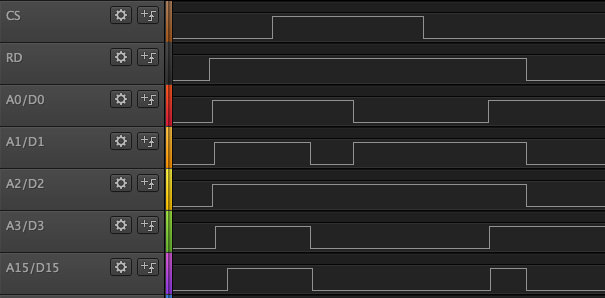
- set
RDtohigh - set
CStohigh - put address on bus
- set
CStolowto latch address - set
RDtolowto put data on the bus - now you can read data from bus
image: Timing Diagram with Program Logic Saleae
If an address has already been set, you can get to the next address as follows.
If no address is set, you have to set one as described in section Non sequential access / latch address.
- set
RDtohigh - set
RDtolowto put data on the bus - now you can read data from bus
We can only put a 16 bit address on the bus with Non sequential access / latch address, because the
Arduino has not enough I/O ports. Every address above 16 bit can be reached with Sequential access
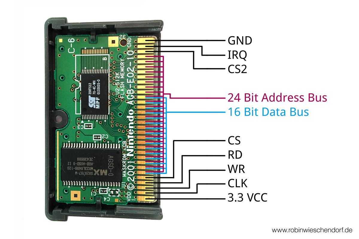
The data / address (D/A) bus pins are between CS and CS2. (... RD, CS, D/A 0 ... D/A 15 ... A 23, CS2 ...). We
only use D/A 0 to D/A 15.
| ROM Pin-Name | Arduino Pin-Name | Atmega328P Port-Name |
|---|---|---|
| VCC | 3.3V | |
| CLK (unused) | (not connected) | |
| WR | GND | |
| RD | 12 | PB4 (PORT-B 4) |
| CS | 13 | PB5 (PORT-B 5) |
| D/A 0 | 2 | PD2 (PORT-D 2) |
| D/A 1 | 3 | PD3 (PORT-D 3) |
| D/A 2 | 4 | PD4 (PORT-D 4) |
| D/A 3 | 5 | PD5 (PORT-D 5) |
| D/A 4 | 6 | PD6 (PORT-D 6) |
| D/A 5 | 7 | PD7 (PORT-D 7) |
| D/A 6 | A0 | PC0 (PORT-C 0) |
| D/A 7 | A1 | PC1 (PORT-C 1) |
| D/A 8 | A2 | PC2 (PORT-C 2) |
| D/A 9 | A3 | PC3 (PORT-C 3) |
| D/A 10 | A4 | PC4 (PORT-C 4) |
| D/A 11 | A5 | PC5 (PORT-C 5) |
| D/A 12 | 8 | PB0 (PORT-B 0) |
| D/A 13 | 9 | PB1 (PORT-B 1) |
| D/A 14 | 10 | PB2 (PORT-B 2) |
| D/A 15 | 11 | PB3 (PORT-B 3) |
| CS2 | 3.3V | |
| IRQ | GND | |
| GND | GND |
I'm not a professional in electronics, but I suspect that the following is important.
Since the outputs of the ROM chip can only pull the voltage to 0V and the high state is an open switch that is not connected (floating), the input of the Arduino must be set to a HIGH value via a pull-up resistor. The outputs of the ROM chip are probably open drain / open collector outputs. The Arduino includes pull-up resistors that can be used for this and that can be switched on via software.

