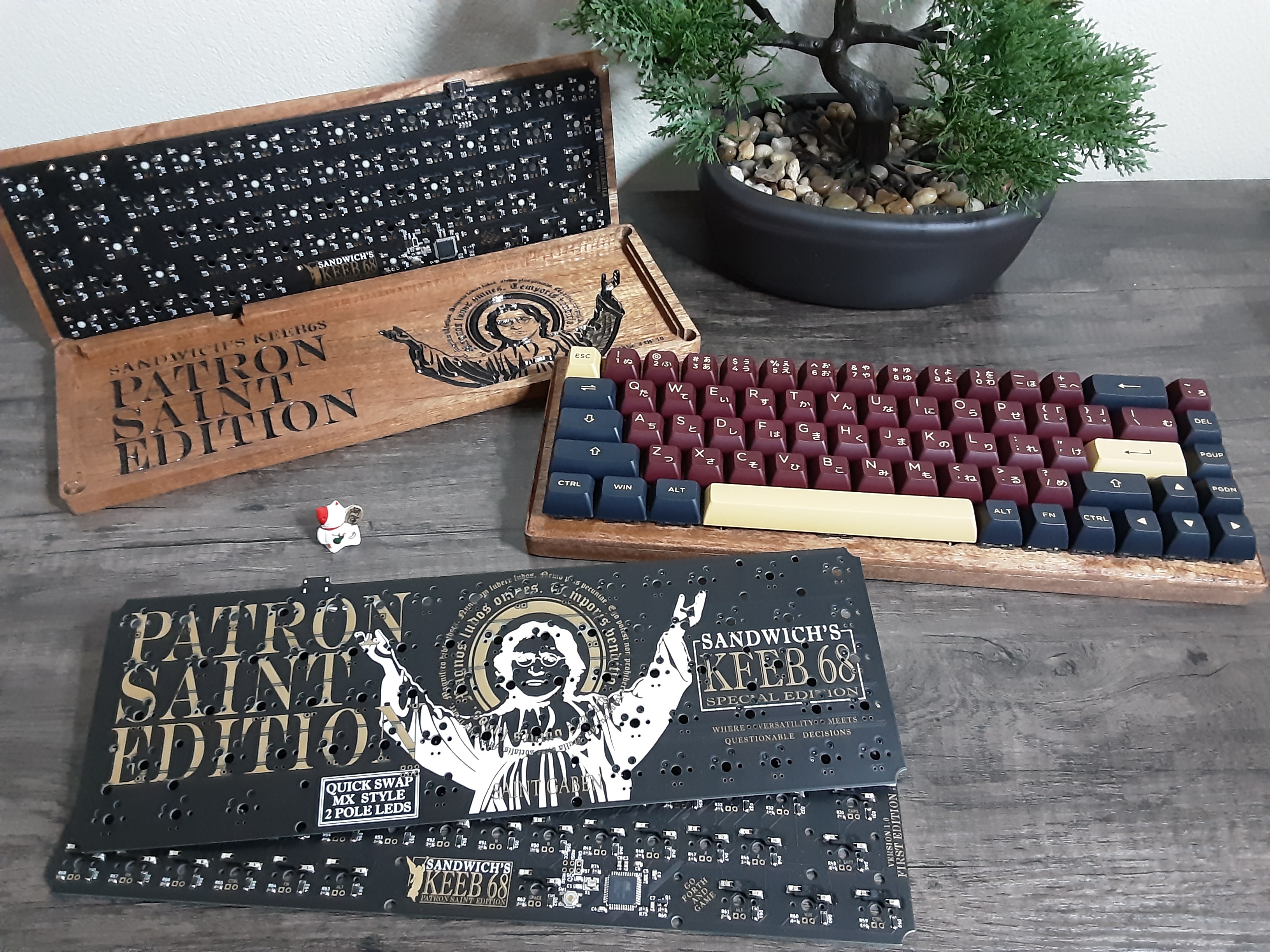
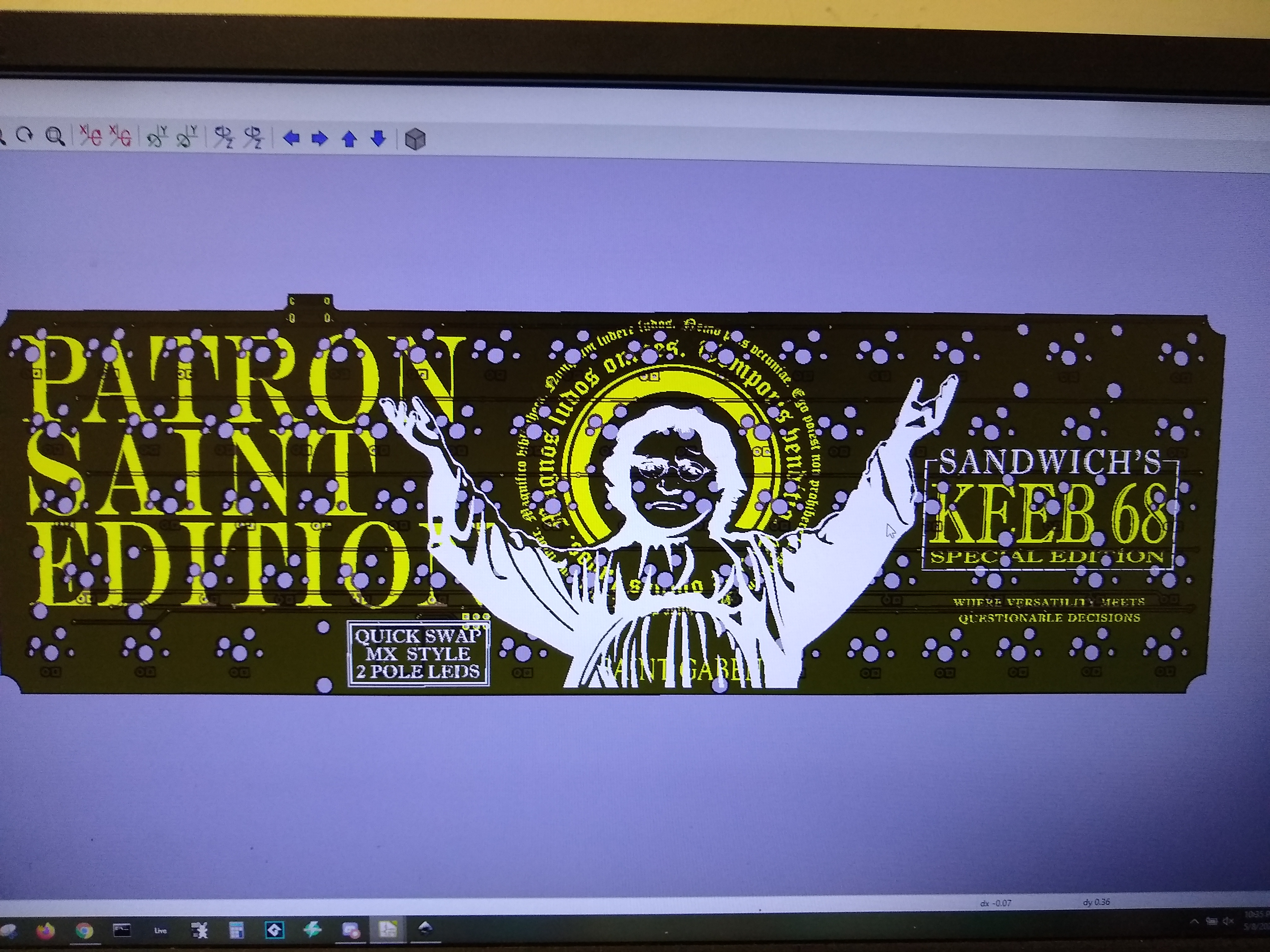
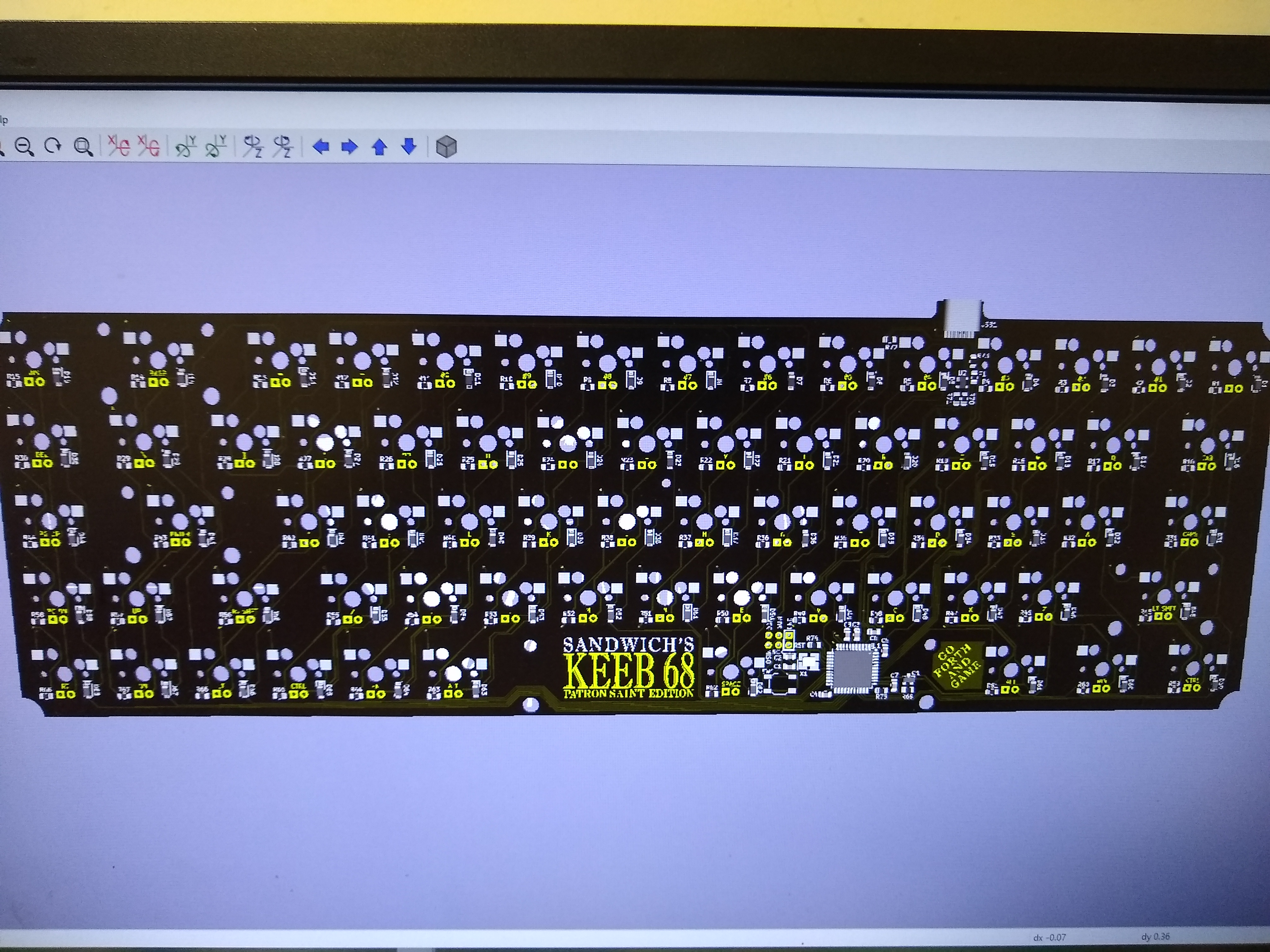
Custom designed tool-free hotswap PCB and Case to make a 68 key keyboard.
This custom keyboard PCB was originally made as a surprise for a friend who enjoys keyboards and turned out well enough that I thought I'd post it back open-source to the community, which is where I also learned from. Specifically, Masterzen and his keyboard design tutorial went a long way in bridging my knowledge gaps and bringing this project to life.
Currently this repo is a buildlog and is being actively updated. It will also include the full keyboard design files once I create new artwork for the open-source release.
I was already familiar in designing with and programming the ATmega32U4 used as the keyboard's brain, and after learning about how to make keyboards using online resources I designed the PCB in KiCad to be compatible with existing QMK firmware using a 68-key layout. The source code for this keyboard has been merged into QMK's repository, and may be found in the online QMK Configurator tool for downloading compiled source, testing the keyboard functionality, defining macros, and changing the layout. Future support for Via is planned.
Once the PCBs and components arrived, a hot air gun and soldering iron were used to assemble and solder the PCBs by hand. A syringe of soldering paste was used along with tweezers to place SMD components that were then heated into place by the hot air gun.
Most of the tools used in assembly can be seen in this picture, except the hot air gun:
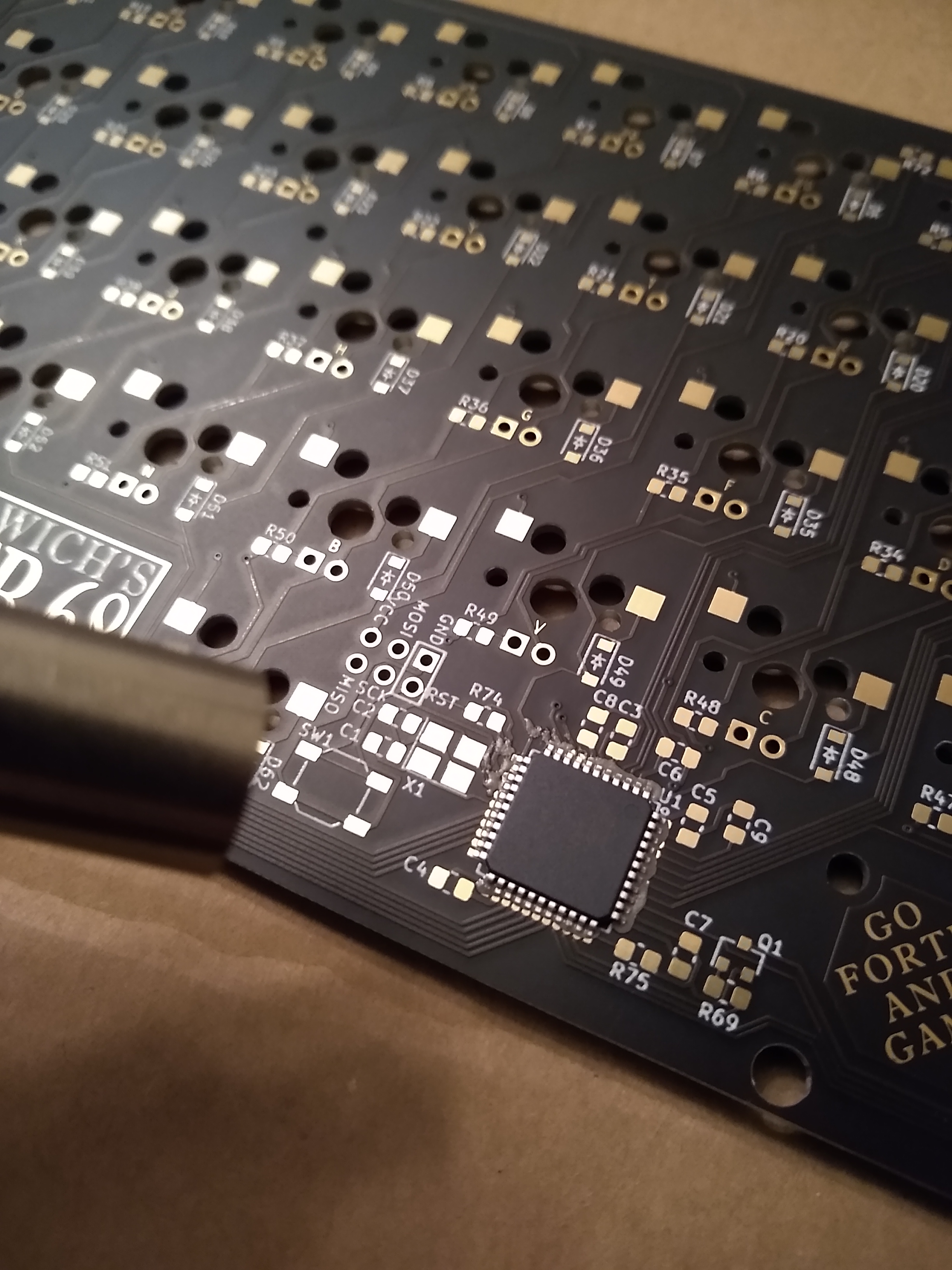
The is a view of the hot air nozzle heating a processor into place:
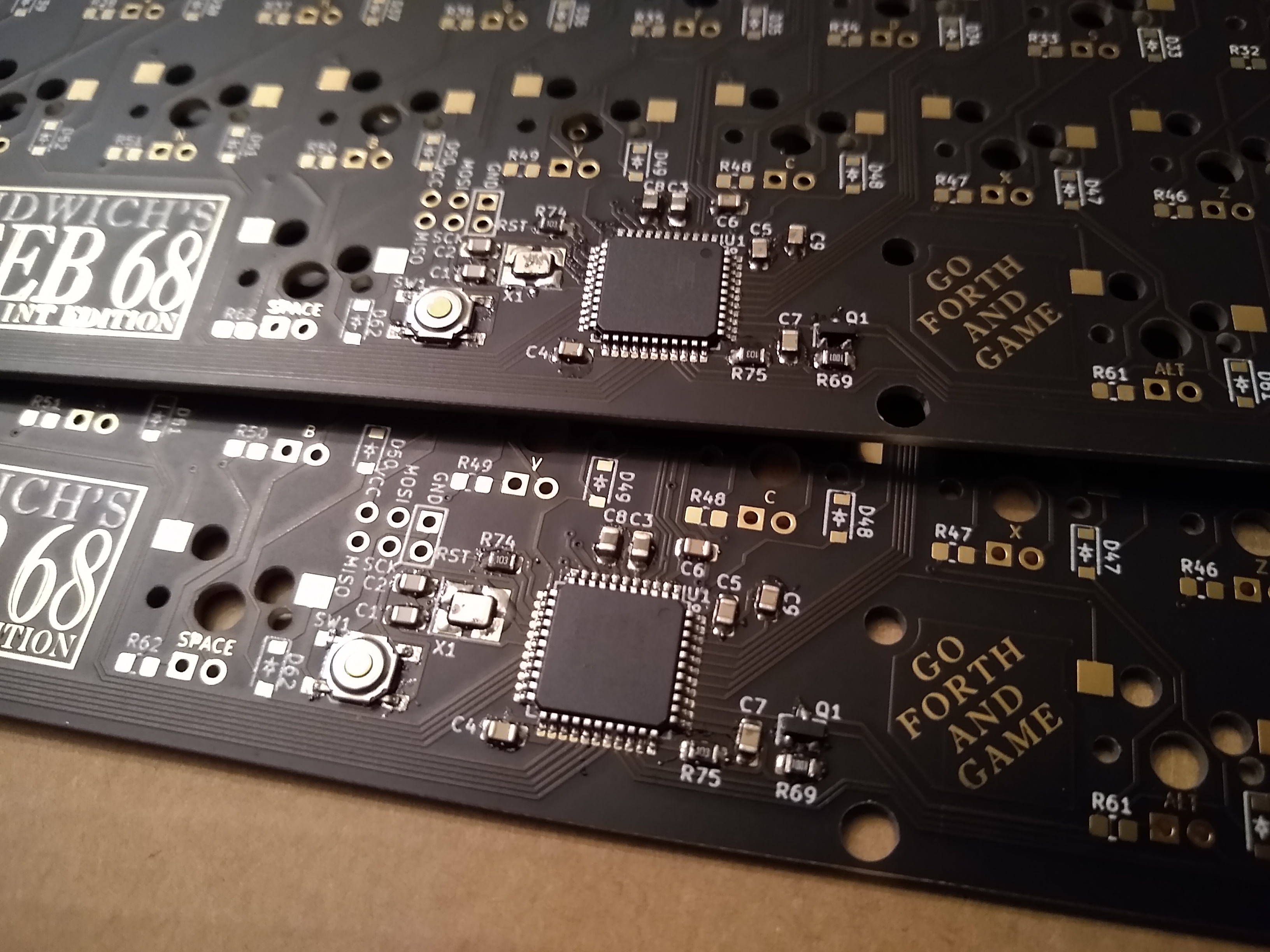
This is a view of two completed keyboard processors soldered into place:
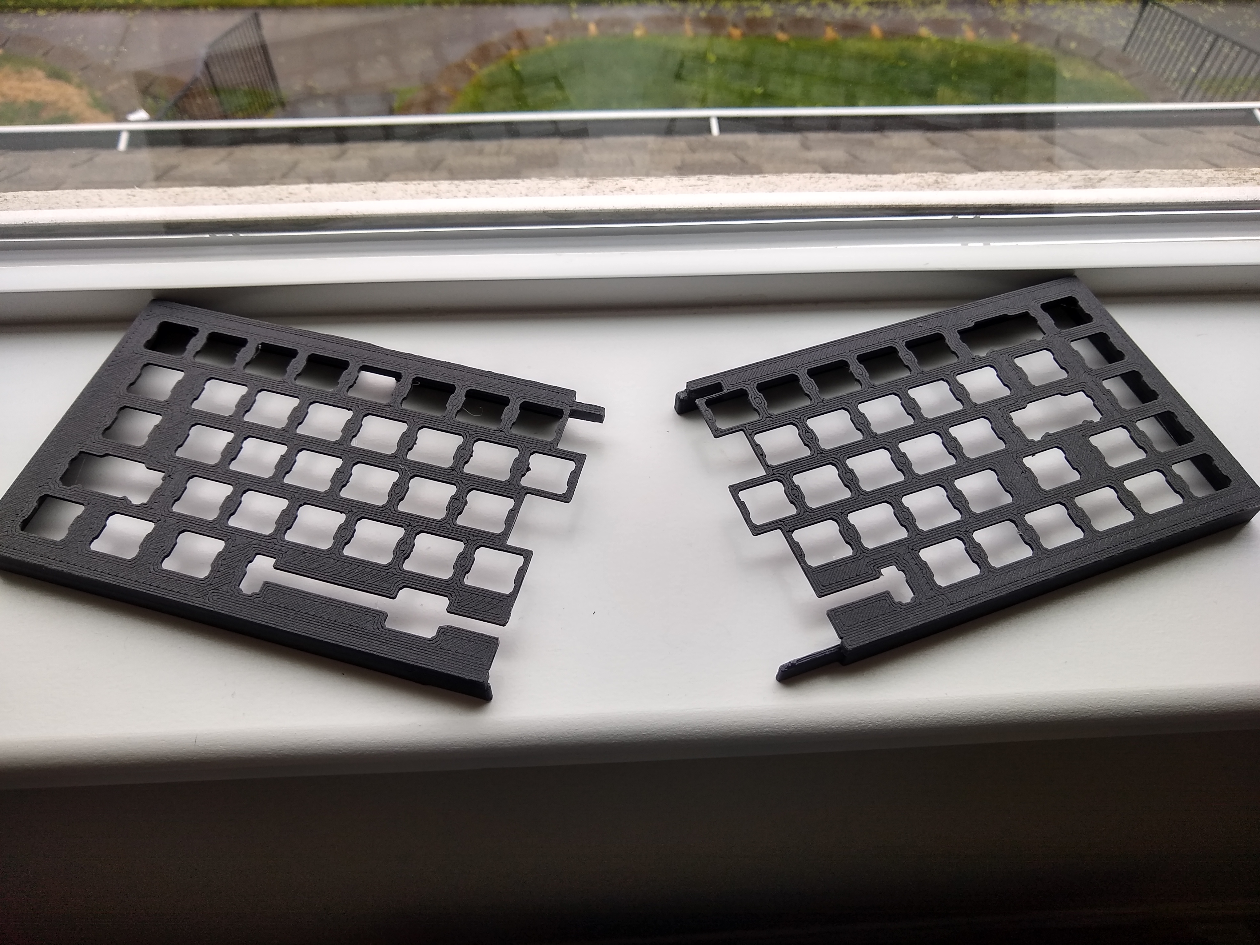
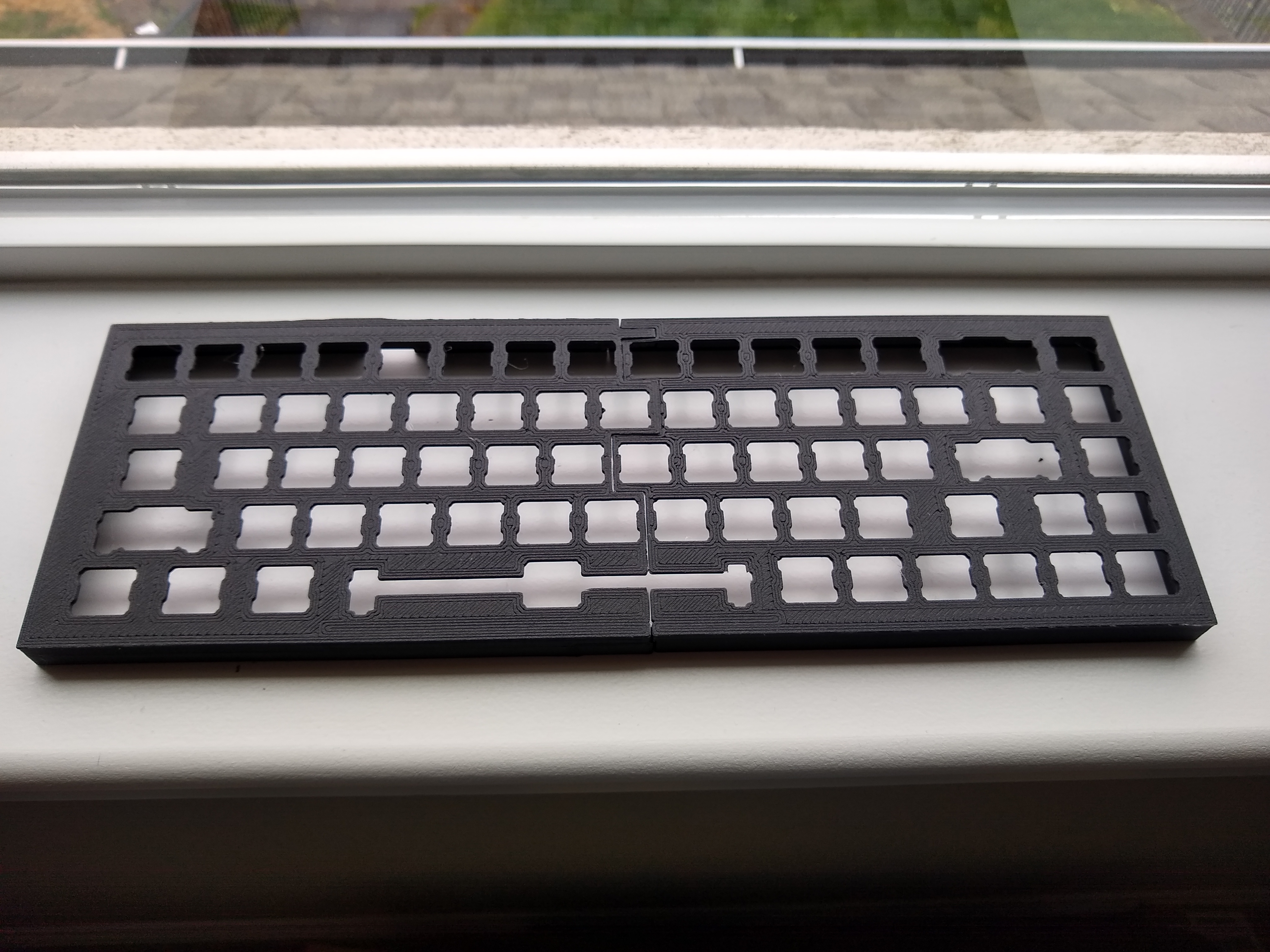
While I soldered the PCBs and worked on the CNC process for the wooden case, my friend quickly designed a 3d printable case to allow us to use the keyboards immediately. The case could be printed in multiple pieces on an ender3 printer, and then metal supports, glue, and heat were used to combine the parts into larger pieces.
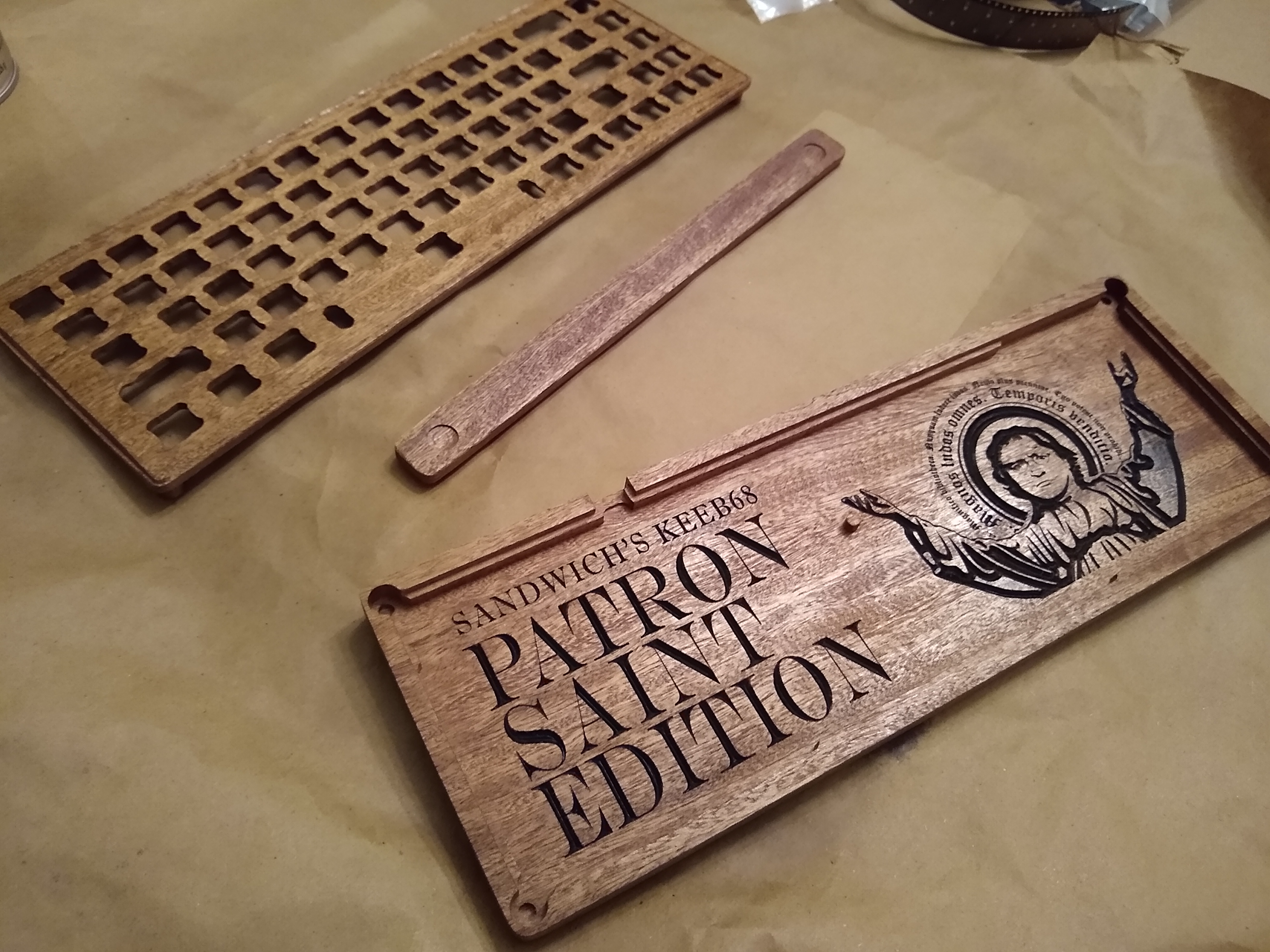
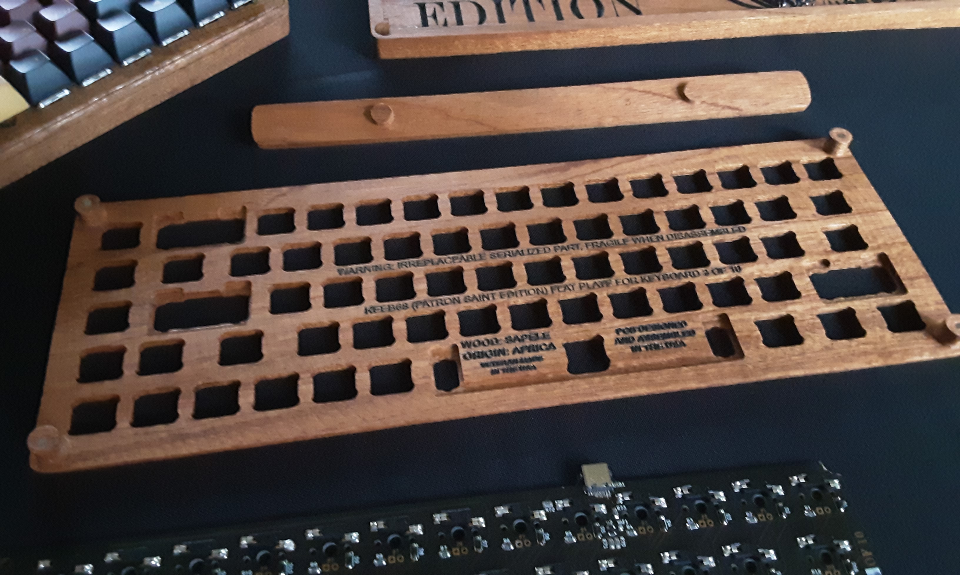
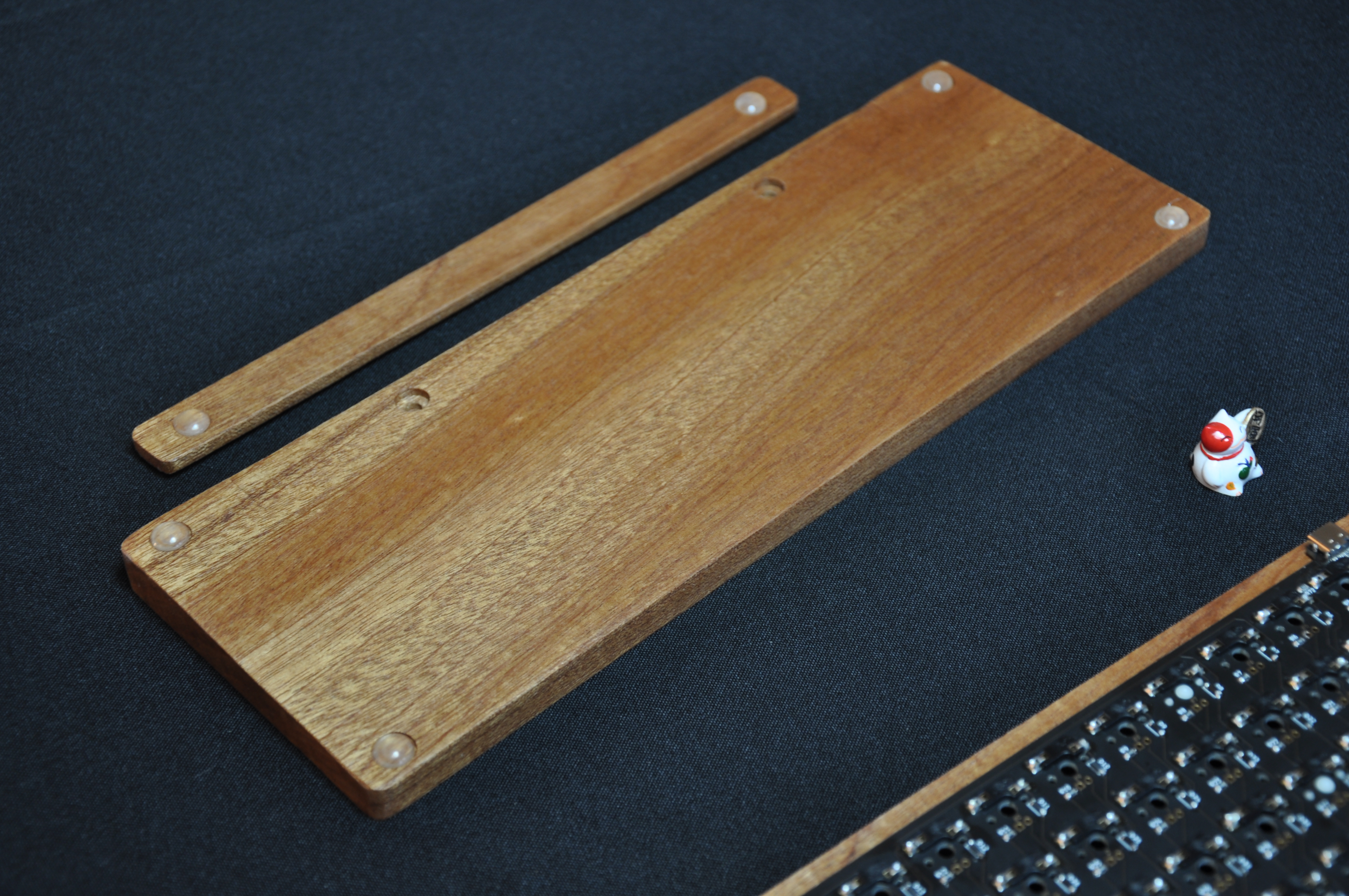
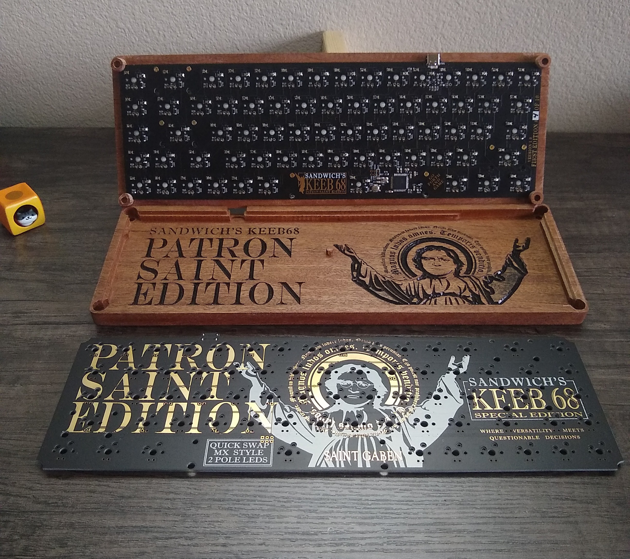
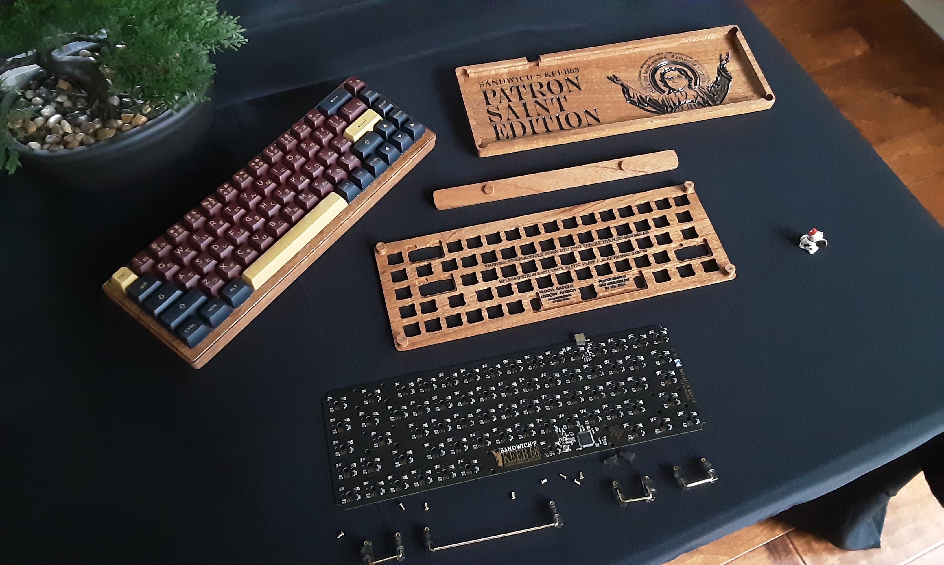
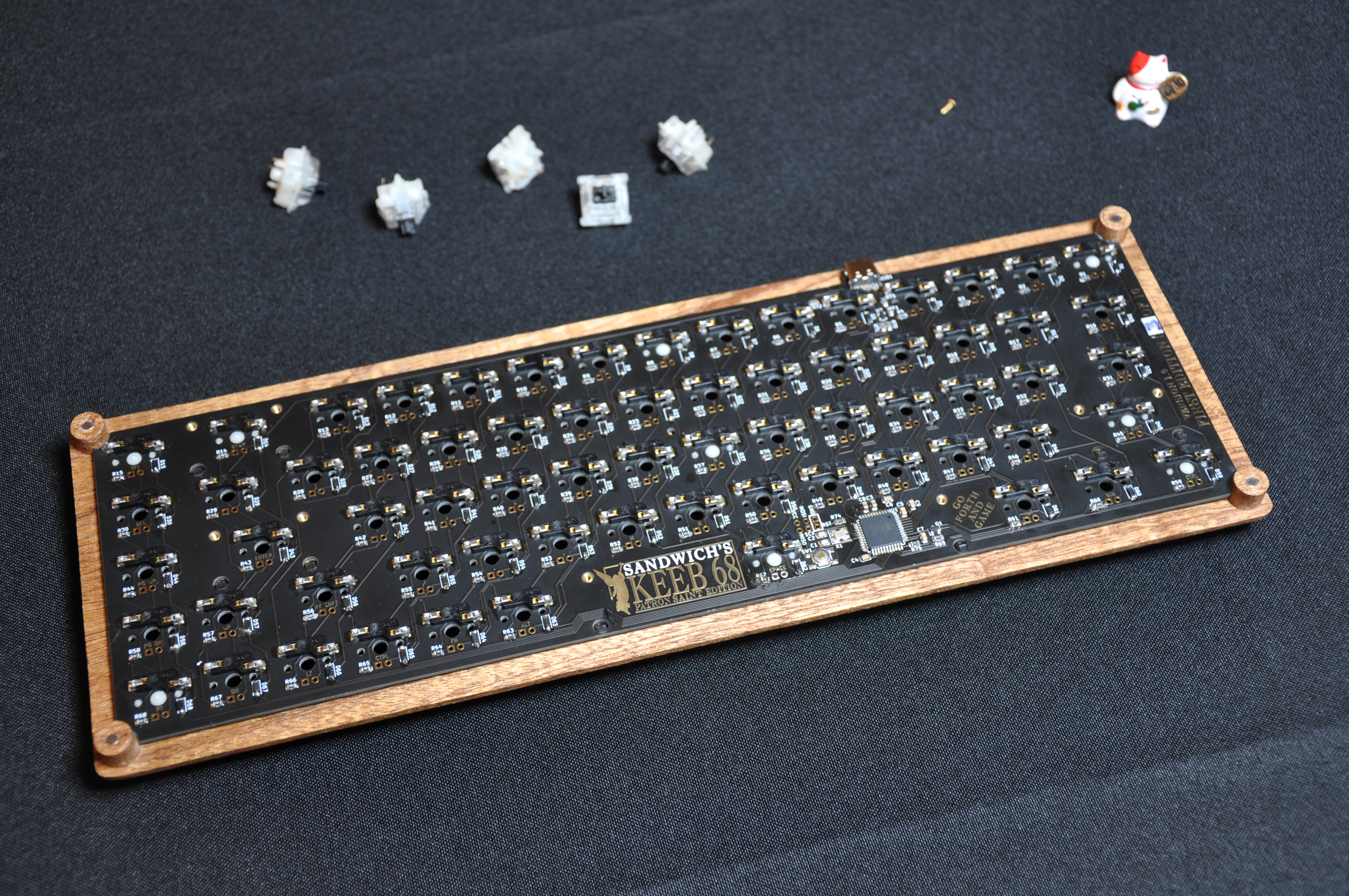
The cases were designed to be cut from two separate pieces of wood stock to make two main parts: a plate and a base. The PCB was designed before the case, leaving the corners cut out in a round shape to aid in future design. This corner space could be used for screw holes, or as in the actual case, alignment posts connected to the plate. The final case design uses these alignment posts on the backside of the plate to hold the PCB in place laterally as well as holding the plate aligned into the base of the case. Between the alignment posts and the tension of the connection to the switches through the hot-swap connectors, the PCB is held firmly in place without screws, appearing to float on the back of the plate. The plate also rests into slots cut into the base to marry the plate, base, and PCB together without screws. This allows the keyboard to be used normally without anything shifting around due to typing, and also allows easy removal of the plate by lifting upward, exposing the inside of the case. Since the PCB is hot-swap designed, and all pieces friction fit together, this allows full assembly and disassembly without any screws (besides the key stabilizers). However, to add LEDs, they must be soldered in as the backlight design was experimental in nature.
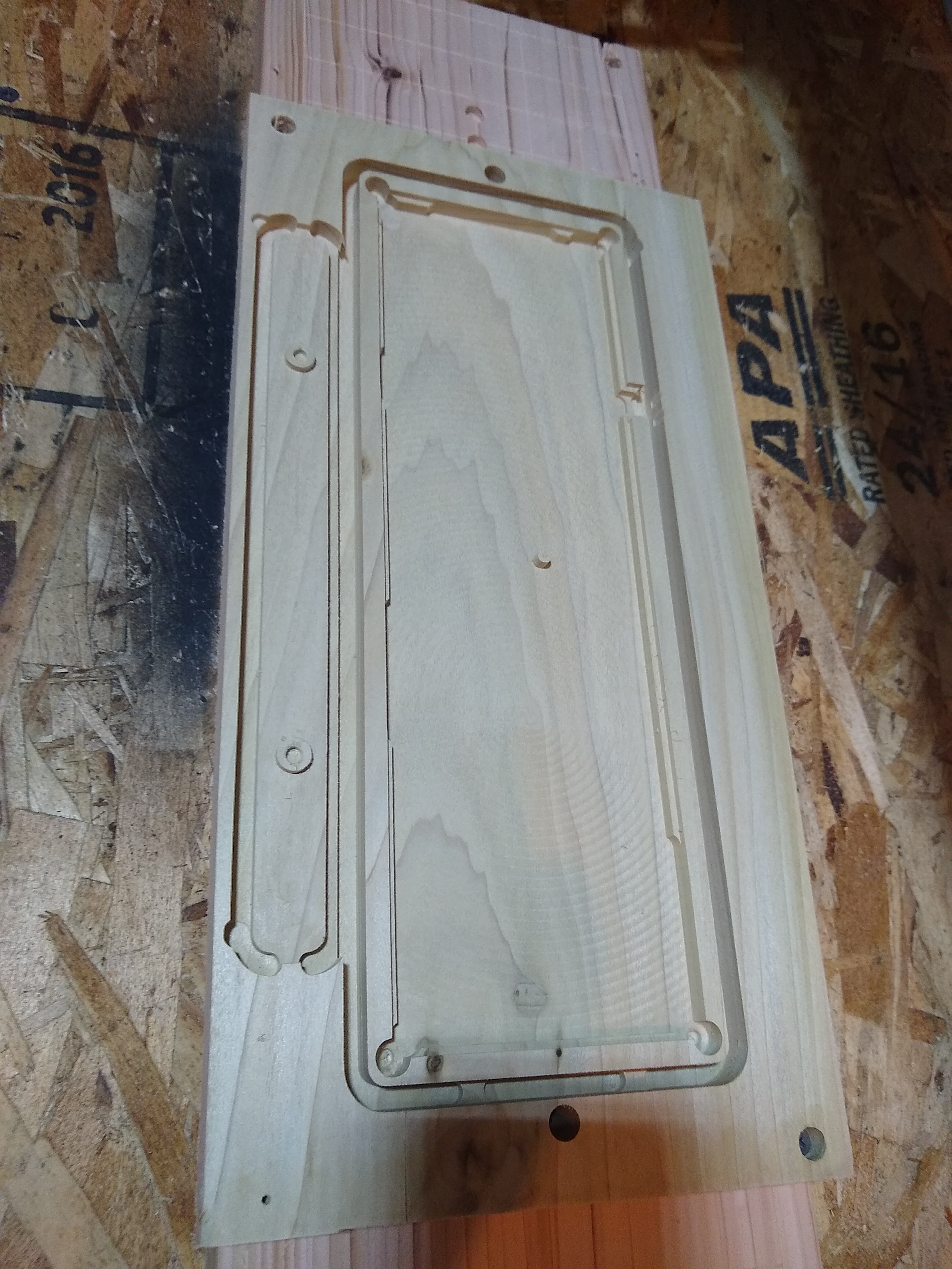
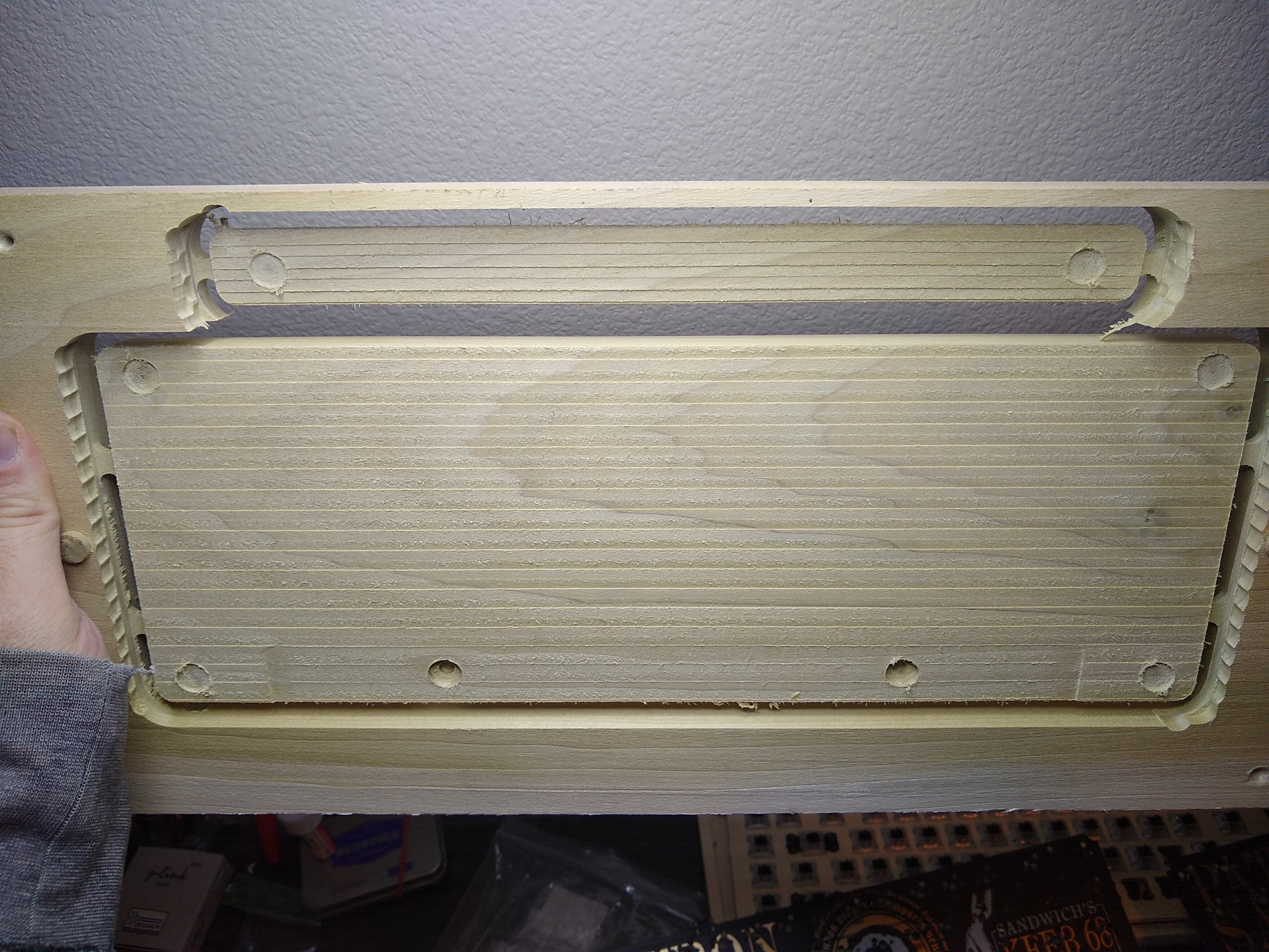
The design of the case required machining both the top and bottom of a blank into a plate or base. A custom technique was developed using alignment pegs at known locations inserted through the piece of stock and into the bed of the CNC machine, allowing dual-sided cutting to sub-mm alignment tolerances. This allowed cutting and then flipping a workpiece to machine both sides of each part accurately.
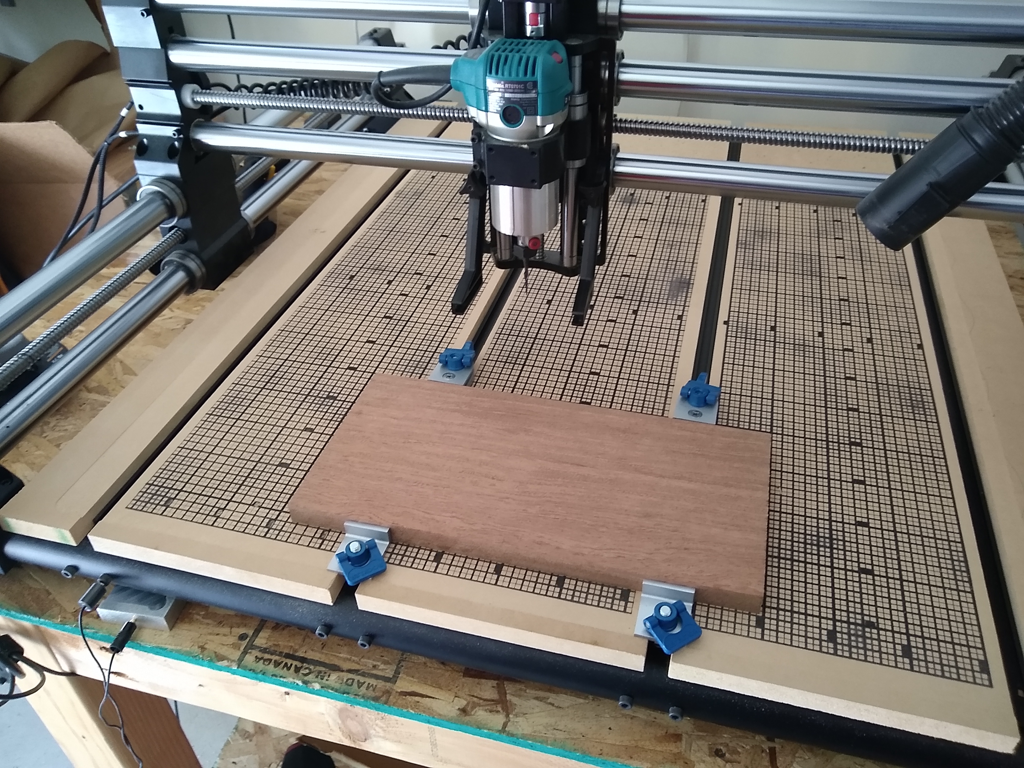
Stock material (sapele wood) used to make a case or plate:
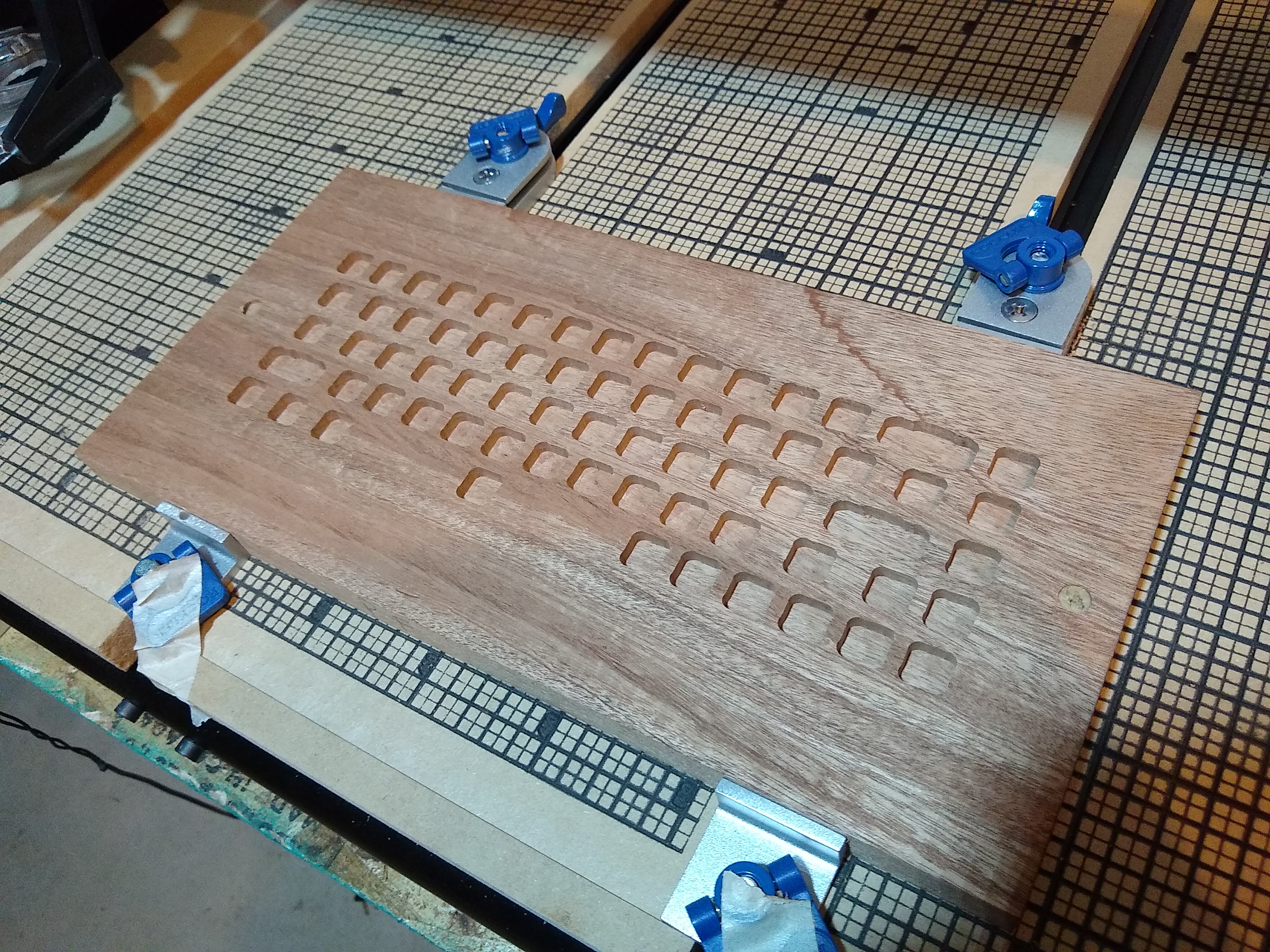
A view of the top cut finished for a new plate:
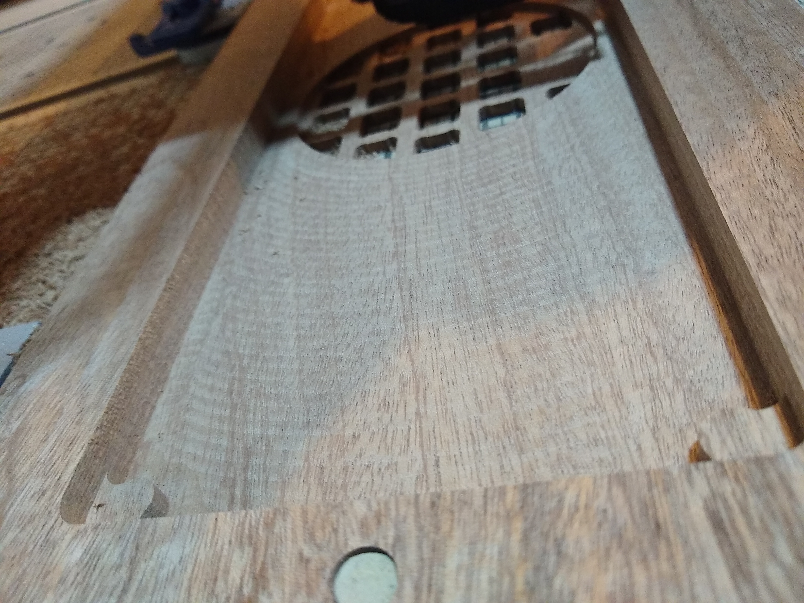
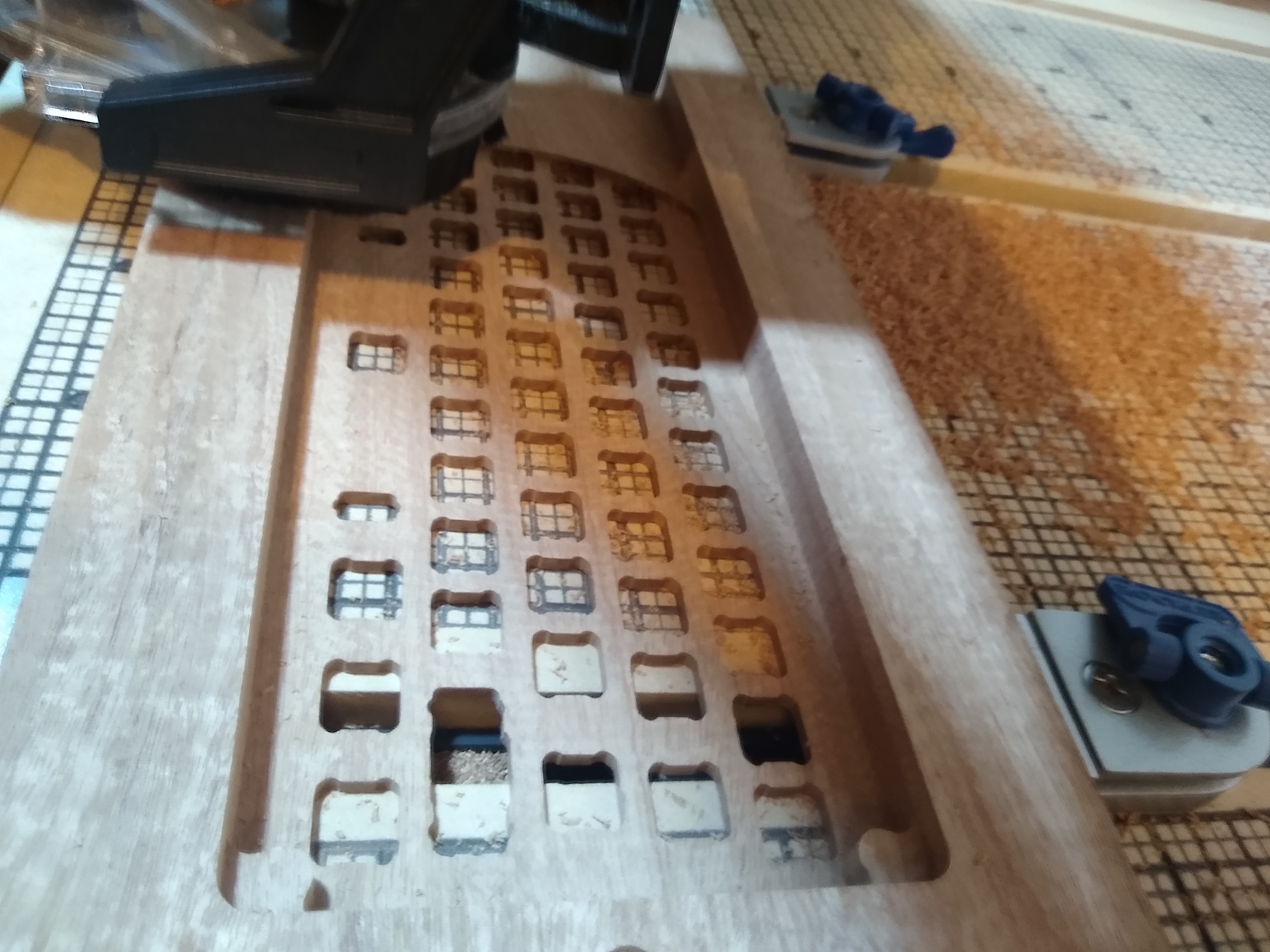
Views of the bottom cut for a new plate, early on and then almost finished:
A lightweight prototype pine case and detachable foot in a machined frame, used to test the cuts for fitment and accuracy:
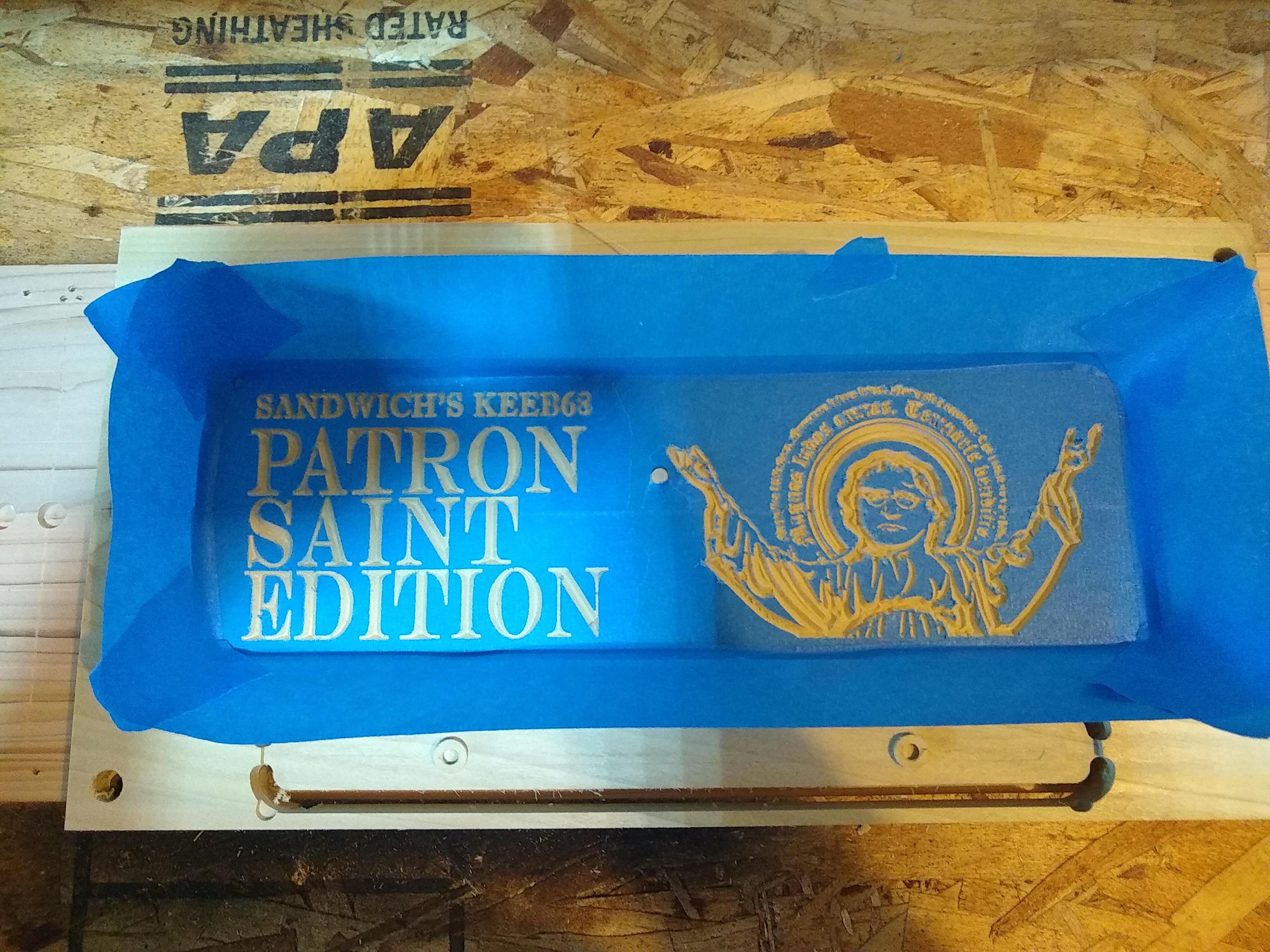
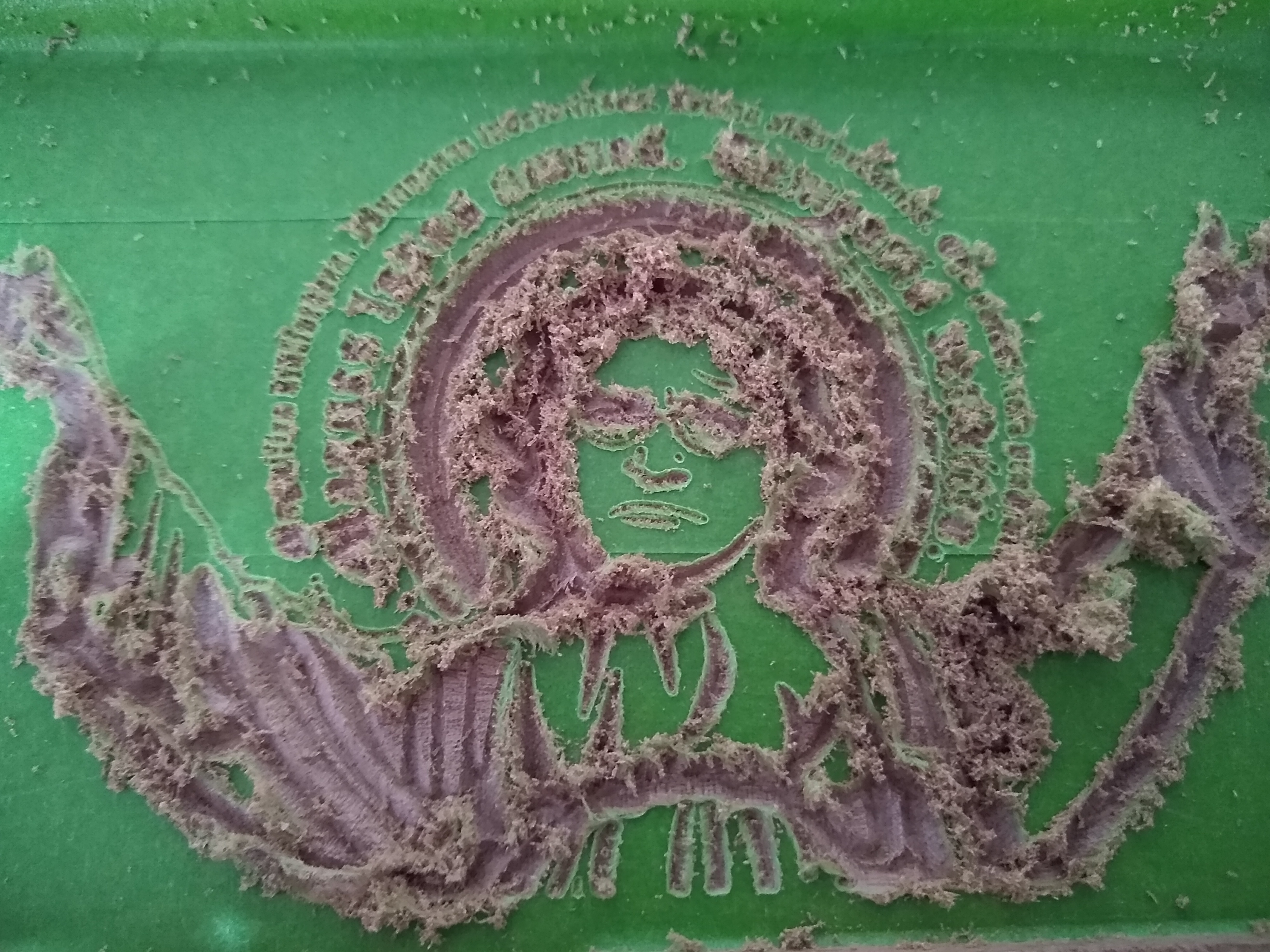
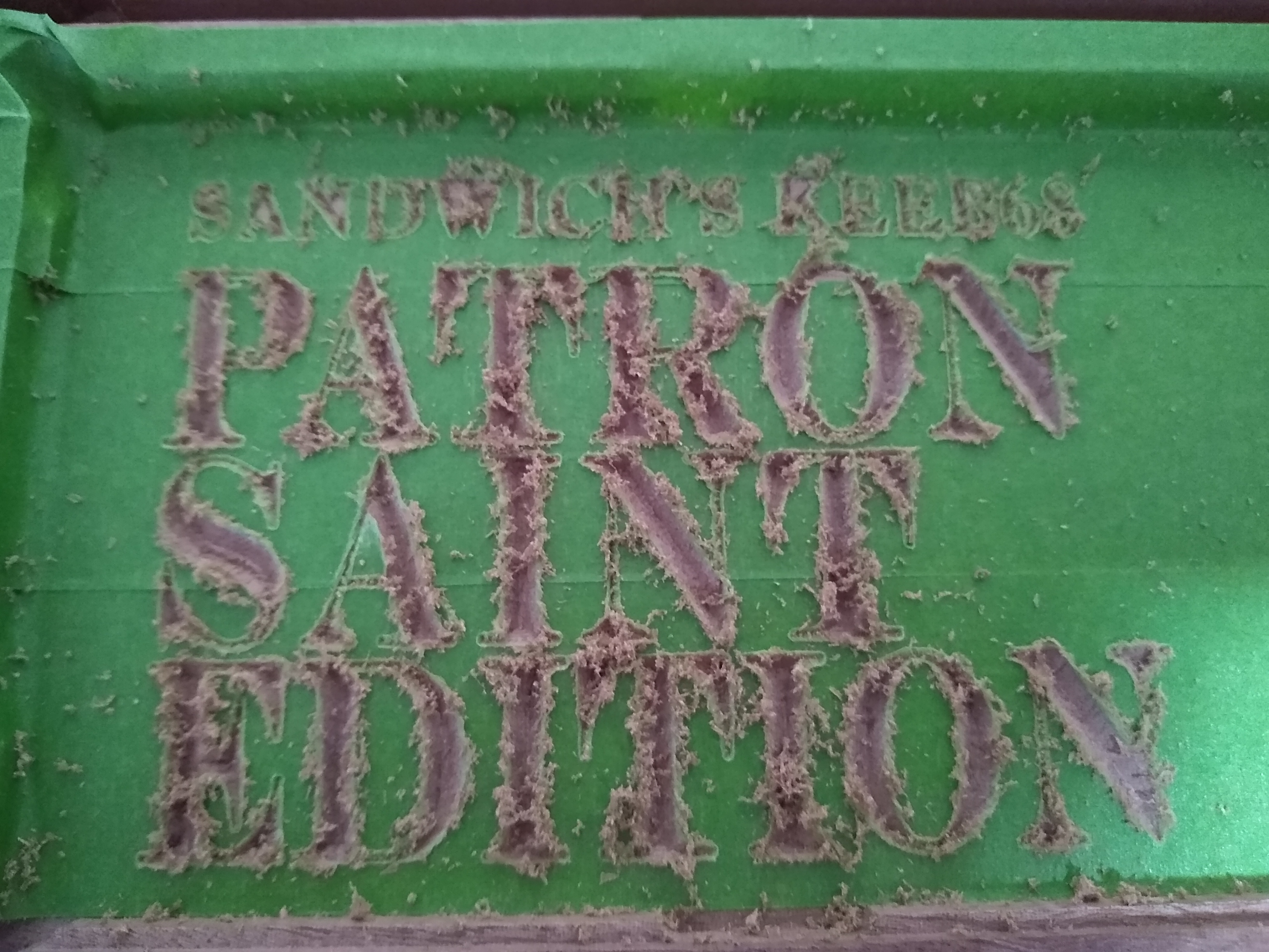
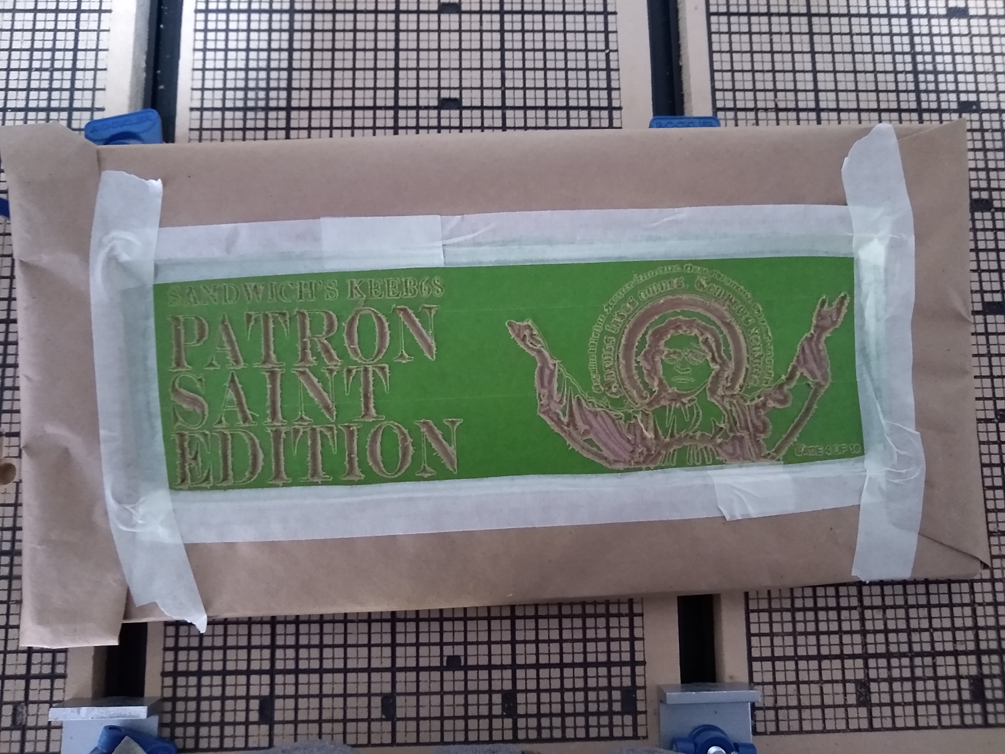
After carving out the inside of the case, the flat surface was layered in painter's tape. The artwork was then CNC engraved through the tape and into the case, leaving a tape mask to paint over. Depending on the specifics of the tape and CNC programming used, there was a varying amount of cleanup work needing to be done to the mask by hand after finishing the CNC carve. The mask was then sprayed with paint and removed, leaving only the engravings painted. A protective polyurethane coating was then applied. The lettering on the backside of the plates was done with the same technique.
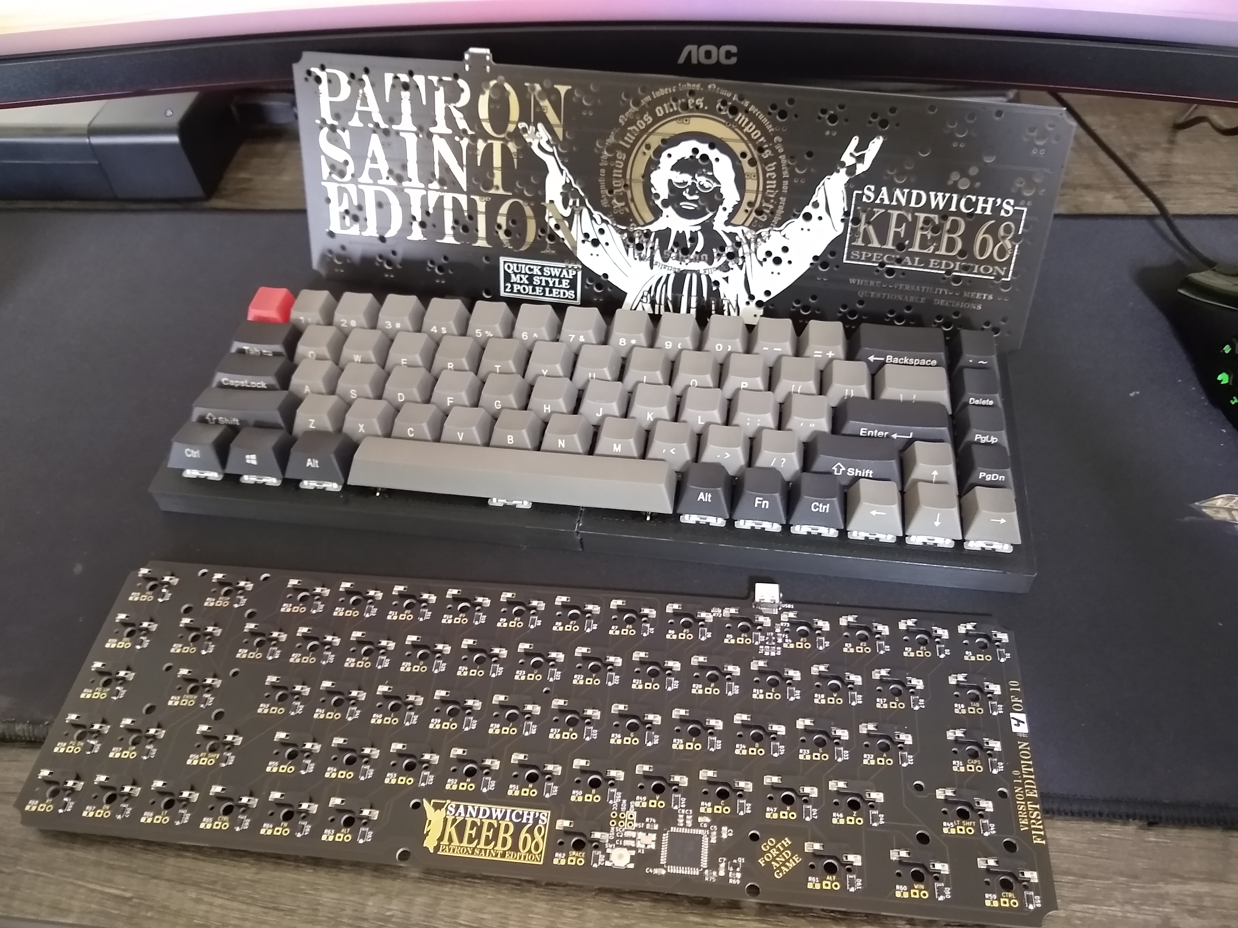
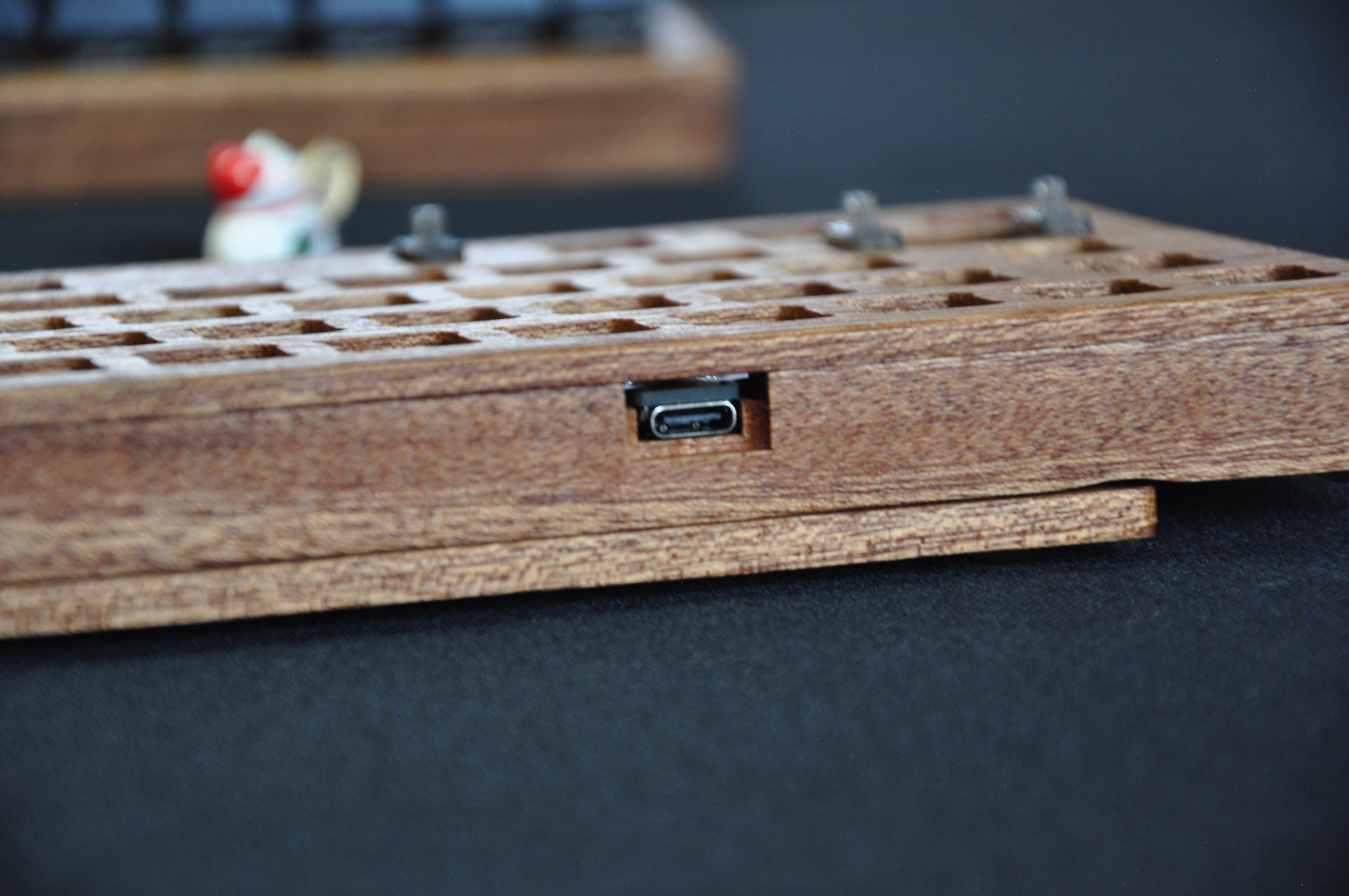
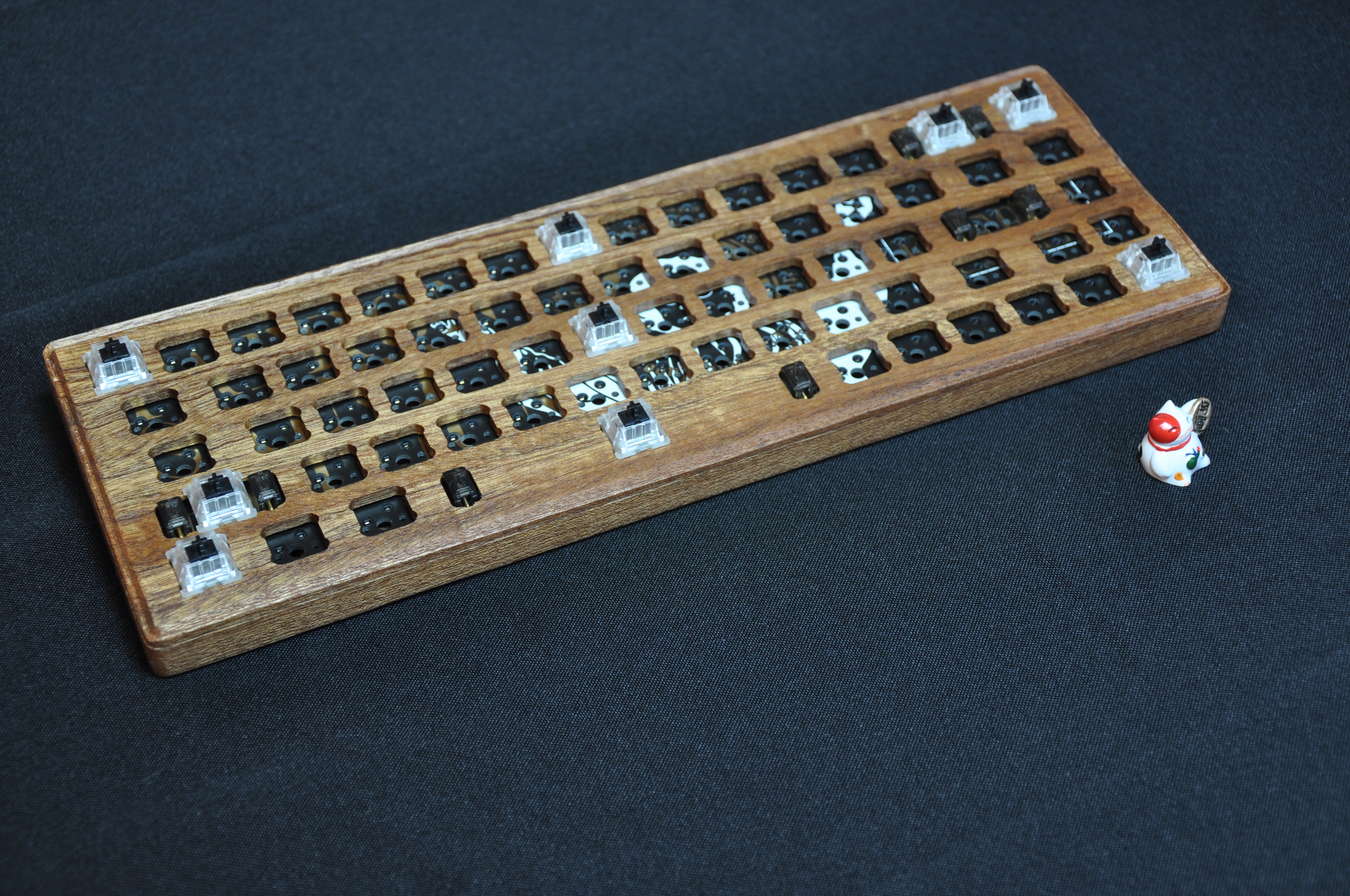
Some additional pictures of the finished keyboards:
There will be more here in the future, including design files for both the case and PCB.
Thanks for taking a look!
