Macro subroutine collection for Eding's Computerized Numerical Controllers, specialized for Sorotec portal milling machines
Please visit my website for an in-depth introduction into CNC macros.
"A Macro or subroutine is a collection of instructions written for the CNC interpreter to perform actions. They are often used to automate recurring operations."
There are many good third party resources out there to learn about writing them, e.g. cnccookbook, too.
The macros provided in this repository are somewhat narrowed to EdingCNC's interpreter and are starting off a 'fork' of the non-version-controlled Standard_Macro_V2-1e by Sorotec.
💡 Idea: When you write a new routine, use of Code M00 might simplify testing your routine. This code will pause the macro and wait for user input (Cycle Start) to continue.
This repository has two folders for assets:
dialogPicturesthat keeps images presented in the dialog message boxesop_f_keythat keeps icons of 'user' macro's function buttons
The images are pulled by EdingCNC based on their file names. For dialog pictures, e.g. the dlgmsg's title parameter has to exactly match the corresponding file name in dialogPictures.
Within the user folder, icon names have to match the corresponding user macro number, e.g. U3 for user sub user_3.
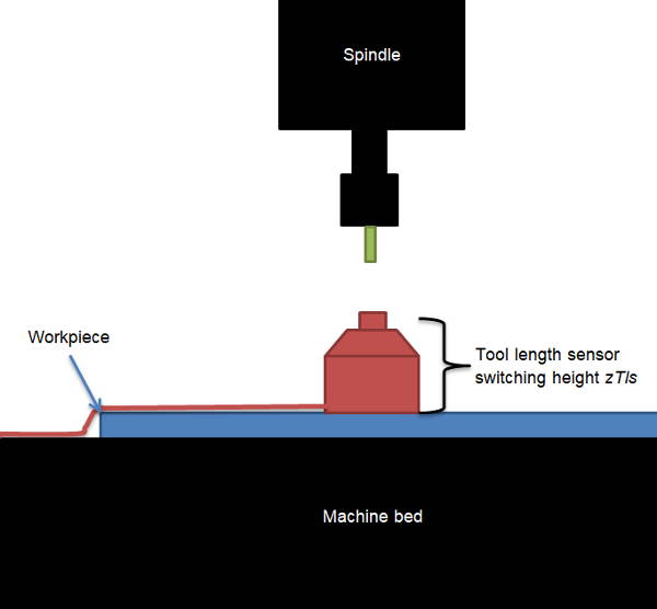
Uses a tool length sensor (alternatively, a 3D edge finder) to detect workpiece surface height.
Sets local G92 working coordinate offset to Z=0 at this place.
Determines tool length in the sense of how long it protrudes from the spindle collet.
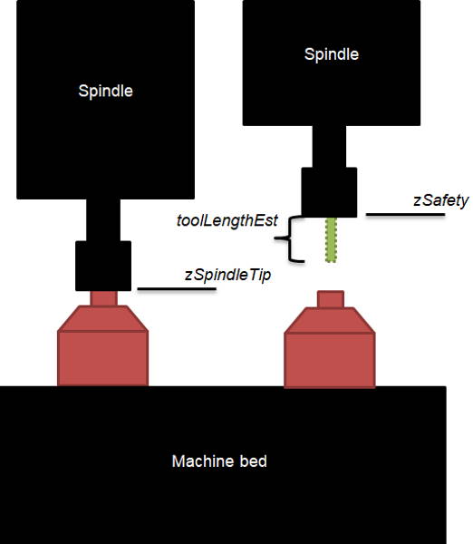
Basically this routine is intended to re-check an endmill's length after a given job, compare it with the value before, and notify the user in case the tool has become "shorter".
Some spindle manufacturers specify a spindle warmup profile. Dwell times and spindle speed can be entered using a config routine so the requested ramp can be executed.
Calls change_tool, continue reading on my blog
Just asks the operator to manipulate the tool, will apply the tool length offset for that tool (no measurement here!)
Geometrical detection of the center of a bore.
In here, you can define where on the machine tool length measurements shall take place, How high the tool length sensor is, enter the position of the spindle collet, define spindle warmup ramp parameters, etc.
Calls all active axes' home routine, order is ZYX ABC
As per EdingCNC handbook R4.03 chapter 3.1 "Systemparameters/ -variables", RS274 NGC defines variables in the range of #1...#5400. Some of those parameters are read-only, some system-specific, some volatile and some others permanent. Let's shed some light here:
- Parameters have the double precision floating point number data type.
- EdingCNC's parameter range is higher than defined in the standard, it ranges until
#5999. - Parameters are nameless which can make writing macros a pretty cumbersome process.
- A parameter can be assigned in a macro file as simply as this:
#100 = 47.11which assigns the number47.11to the parameter with ID#100. - A parameter can be evaluated with different statements, example:
IF [[#5011] == [#5008]] THEN ...for a deeper syntax overview, please refer to the EdingCNC handbook.
Variables in range #26...#3999 are volatile and can be used by the programmer to store data temporarily. The data assigned in this range is deleted on power off or in the event of an alarm/emergency stop.
The variable range #4000...#4999 are stored permanently on the system. They are free to be used.
They keep their value also when powered down, after an emergency stop etc.
EdingCNC uses some of these variables per default, e.g. #4995...#4999.
| ID | name | description |
|---|---|---|
| #4995 | toolLengthSensorHeight | Saves height of tool length sensor for correctly setting Z-zero |
| #4996 | toolLengthSensorFlyover | Safety height above tool length sensor (recommended: machine Z0) |
| #4997 | toolLengthSensorPosX | X-position of the tool length sensor |
| #4998 | toolLengthSensorPosY | Y-position of the tool length sensor |
| #4999 | toolLengthSensorChuck | Switching point of the tool length sensor when no tool in spindle |
Generally speaking, the variable range from #5000...#5999 should be avoided by the programmer - most of them are used system-internally or have intentionally been left blank.
- #1...#26 ; Code for letters where
#1=A,#26=Z. Can be used in subroutines and macros. - #5001...#5006 ; Current machine position where
#5001=X-axisand so on. - #5008 ; Current tool number
- #5009 ; Current tool's radius
- #5010 ; Current tool's Z-offset
- #5011 ; Incoming tool number on tool change
- #5012...#5014 ; Current tool's G43 offset (tool table)
- #5051...#5056 ; Sensor position in machine coordinates
- #5061...#5066 ; Sensor position in work coordinates
- #5067 ; Flag that is written to
trueif sensor has triggered during a Z-sensing runG38.2 - #5068 ; sensor's trigger point on Z-axis (machine coordinates)
- #5069 ; Handwheel step count
- #5070 ; spindle speed
Sinr/sec - #5071...#5076 ; Current machine position (machine coordinates)
- #5081...#5086 ; Sensor position in joint coordinate system
- #5101...#5106 ;
MCAMachine Change Area negative limit: Area the machine may not penetrate in normal operation, e.g. to protect vices - #5111...#5116 ;
MCAMachine Change Area positive limit - #5121...#5126 ; Machine's home position (machine coordinates)
- #5131...#5133 ;
TCATool Change Area negative limit: Area the machine may only access for tool changes - #5242...#5143 ;
TCATool Change Area positive limit - #5150 ; Machine's coordinate type.
1 = Trivial/Cartesian2 = 4th axys cylinder as Y-axisVirtual C-axis4-17 = reserved18-30 = user defined - #5151 ; flag showing
ZHCZ-height compensation status wheretrue = active - #5152 ; flag showing Spindle status where
true = on - #5161...5166 ;
G28parking position one's axis values (machine coordinates) - #5181...5186 ;
G30parking position two's axis values (machine coordinates) - #5190 ;
G68flag showing rotation of coordinate system wheretrue = active - #5191...#5193 ; Axis rotation point (machine coordinates)
- #5194...#5196 ; Axis rotation angle around rotation point
- #5200 ; flag showing
G51scaling of coordinate system wheretrue = active - #5204 ; Non-uniform scaling: scale factor X
- #5205 ; Non-uniform scaling: scale factor Y
- #5206 ; Non-uniform scaling: scale factor Z
always 1.0 - #5390 ; flag showing active Spindle selection,
M90 = 0M91 = 0M92 = 2,M93 = 3, default 0 - #5391...#5393 ; active spindle offset X-Z
- #5394...#5397 ; maximum spindle speed for spindles
0...3
@TODO: Add asset folder for icons and show images of macro execution within EdingCNC.