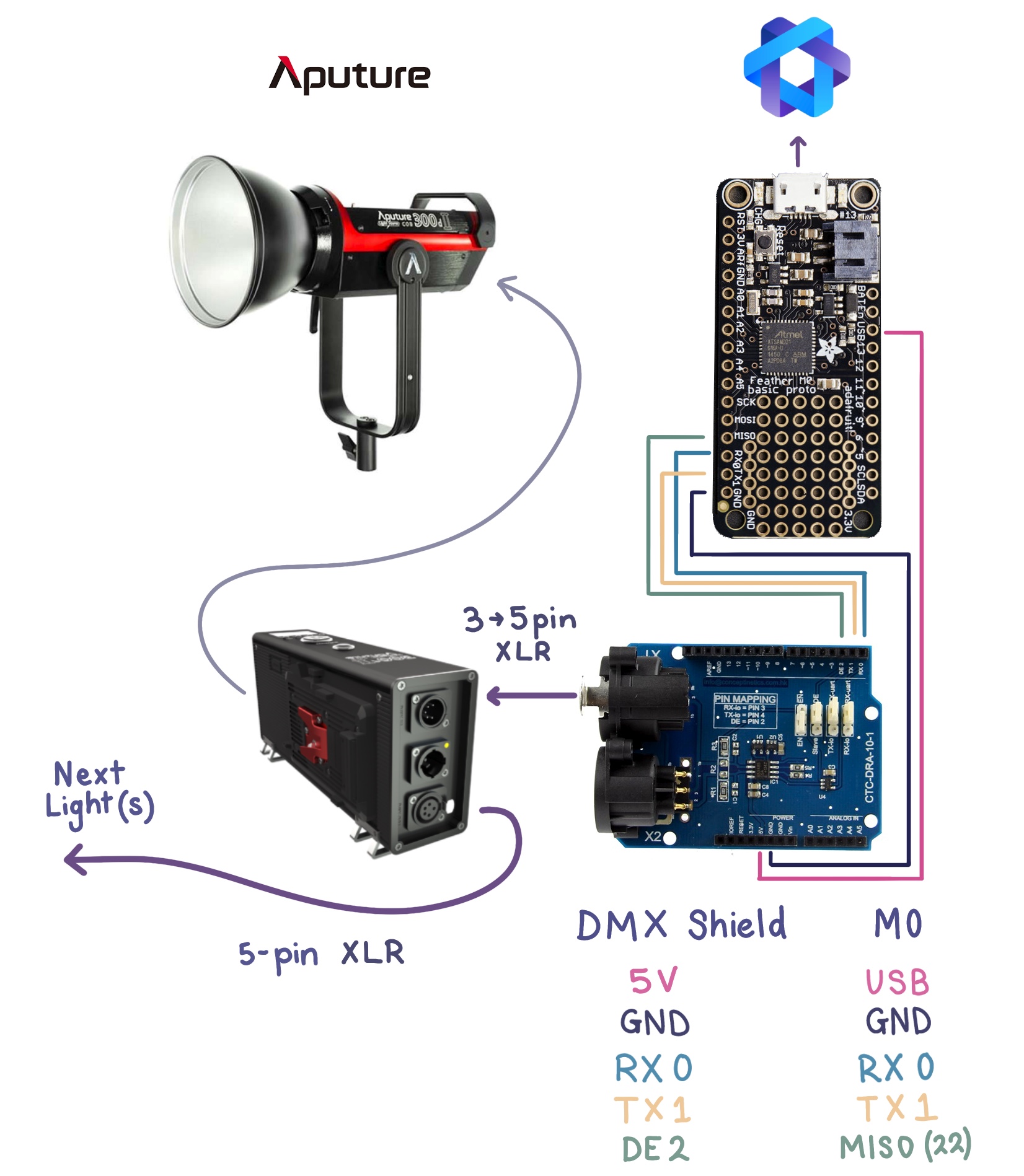
This repo contains the quick and dirty implementation for computer control of some Aputure Lightstorm fixtures (video lights) over DMX.
I use this to control a pair of lights in time-lapse video, allowing smooth brightness ramps across frames as other systems handle motion etc.
-
Aputure lighting fixtures which support DMX-512 control (120DII and 300DII used),
-
DFRobot DMX Shield, I bought mine from CORE Electronics
-
DMX cables (XLR). I made my own with locally sourced parts.
- 3-pin XLR to 5-pin XLR cable,
- 5-pin XLR to 5-pin XLR cable if chaining multiple fixtures,
The DE (pin 2) control pin can be moved to any GPIO, just ensure the SAMD21DMX.setDirectionPin(22); line in the firmware is updated to match.
I tried using the shield with an Arduino Uno and wasn't satisfied with the quality of the DMX waveform, or the use of timers and the only hardware UART peripheral.
Additionally, the shield's design intent/recommendation to use 8-bit AVR based Arduino's is not ideal post 2020, as the range/availability and capability of ARM microcontrollers provide a superior prototyping experience. Not needing to swap the enable jumper on the shield each time you program the micro is a great QoL improvement.
Instead, the LSXAMD21DMX library by claudeheintz was used with the M0 proto.
The firmware also depends on the electricui-embedded library which handles communication with the PC control interface, or serial commands from another microcontroller.
Each fixture requires 5 addresses for control. Use setMaxSlots to configure the output range. This was set to a smaller value than the 512 addresses supported, as it increases the output frequency (and reduces memory consumption).
During setup(), the calls to LSXAMD21DMX are relevant:
SAMD21DMX.setDirectionPin(22);
SAMD21DMX.setMaxSlots(16);Fixture abstraction is achieved with the array of AputureLS_t structures, where an enum value is used to reference the fixture in the array in a human friendly manner.
Add an additional entry to the LSFixtureNames enum to add an additional light.
enum {
    LS_C300D2 = 0,
    LS_120D2,
    LS_NUM_FIXTURES,  // must be last entry in enum
} LSFixtureNames;

AputureLS_t cob_fixtures[ LS_NUM_FIXTURES ] = { 0 };
// somewhere in your code
cob_fixtures[LS_C300D2].intensity = 64;
cob_fixtures[LS_120D2].intensity = 128;At the moment, committing the structure to DMX isn't dynamic for n light fixtures, as the fixture's base address isn't dynamically configured.
commit_aputure_to_dmx( 1, &cob_fixtures[ LS_C300D2 ] ); where 1 is the DMX address of the light.
- Open the
/firmware/firmware.inosketch with the Arduino IDE. - Set the board to
Adafruit M0and choose the relevant port. Read this if you need help. - Click upload.
- The red LED on the M0 should be blinking to indicate operation.
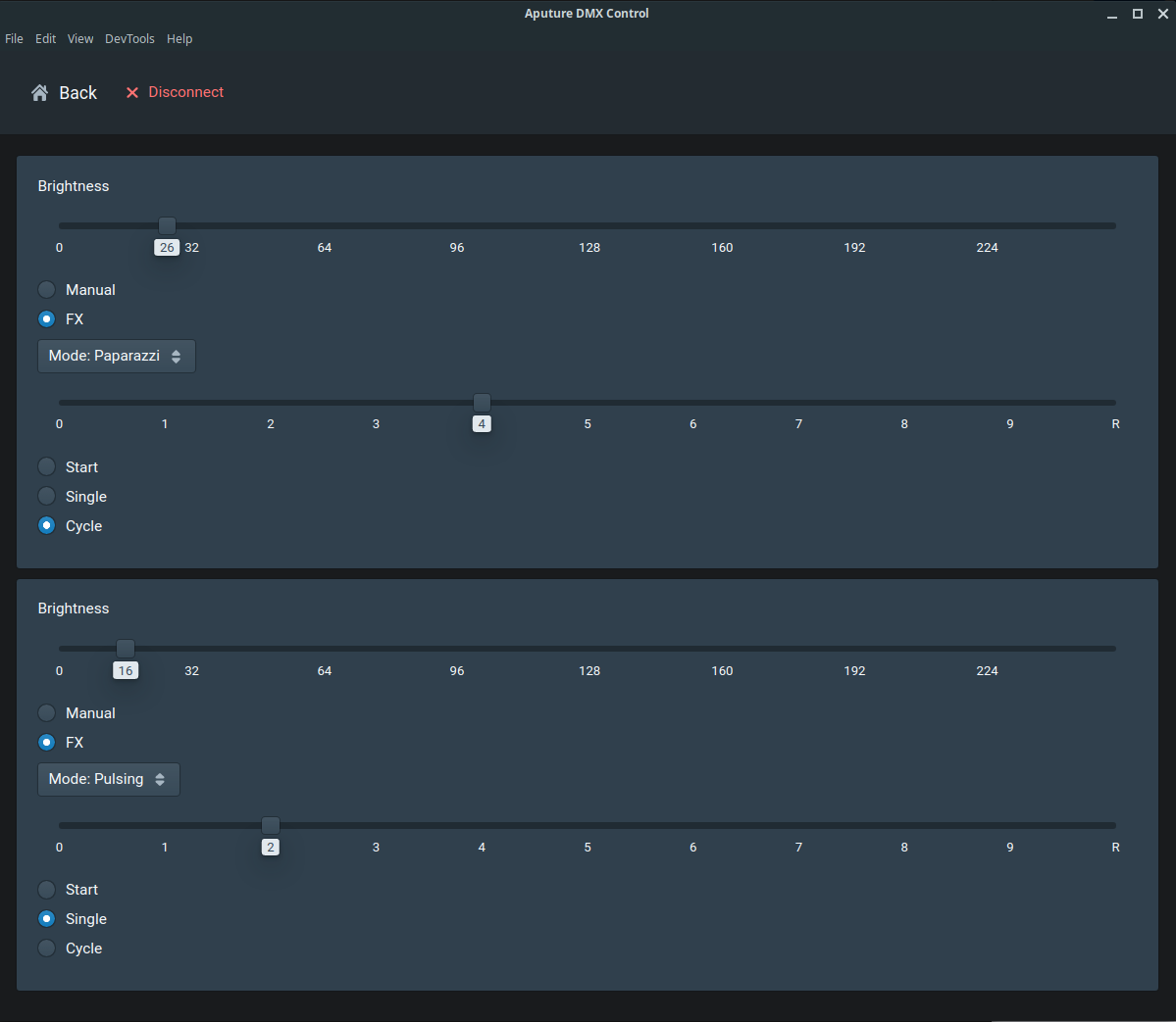
The actual interface is rather simple and was made in about 20 minutes - just slider for brightness control and settings to configure the various inbuilt lighting effects (mode, frequency and start/repeat controls).
The UI will automatically create a control card for each of the number of fixtures configured in firmware.
With Electric UI tooling installed, from your shell:
- Navigate to
/interface arc installto pull the dependanciesarc startto launch the Electron sandbox environment and connect to the M0 over USB.arc buildwill generate a binary bundle for your OS to simplify startup/distribution if needed.
The main UI layout as shown in the above screenshot can be found at /interface/src/application/pages/DevicePages/OverviewPage.tsx.
The 'fixture structure' and mode enums are defined in /interface/src/application/typedState.tsx, and the codec to handle the C-structure conversion is in /interface/src/transport-manager/config/codecs.tsx and should be pretty self explanatory.

