Video demo: https://www.youtube.com/watch?v=K29czbRWfgs
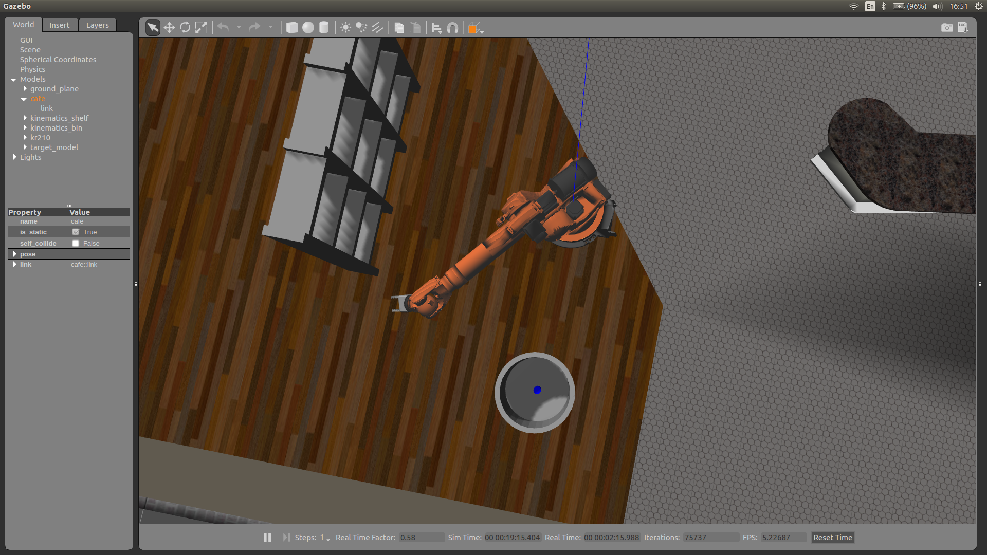
Image with the item in the bin:

My notes from the project:
The most difficult part in the project was refreshing the inverse kinematics. Once I had understanding of it the rest was more or less straightforward.
Also I had some tech issues with the ROS setup. I decided not to use the VM environments as it was too slow on my laptop. So I had to deal with some missing dependencies issues and Python compatibilities. I managed to make all work only with Python2.7, but initially I had Python3.6. Even in native setup it is not as fast as I wish it is. Rviz works at something about 10 FPS on my i7-based laptop (even in demo mode without my code). Not sure if it is something expected or something is wrong in my setup.
As you can see from the video the movements of the arm are not smooth and has some unnecessary rotations. Not sure what's the reason for that. My best theory would be that we are using Euler angles instead of quaternions. I know that the later are much better for approximating movements smoothly. Based on the discussion on slack this seems to be a common problem.
A few things I would like to improve (when I have time):
- figure out and fix the problem with auxiliary rotations of the arm joints
- optimize the code by switching to Numpy and saving matrices between function calls
- implement the Jacobian IK method to compare it with the implemented method
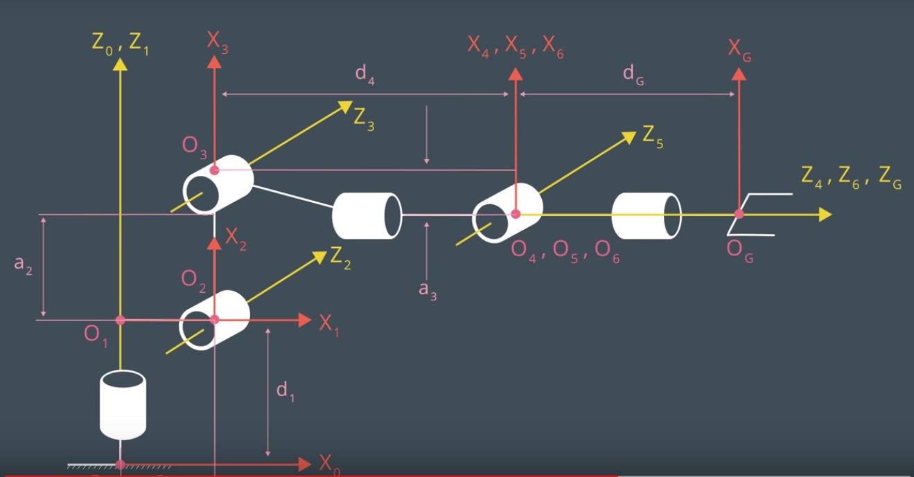
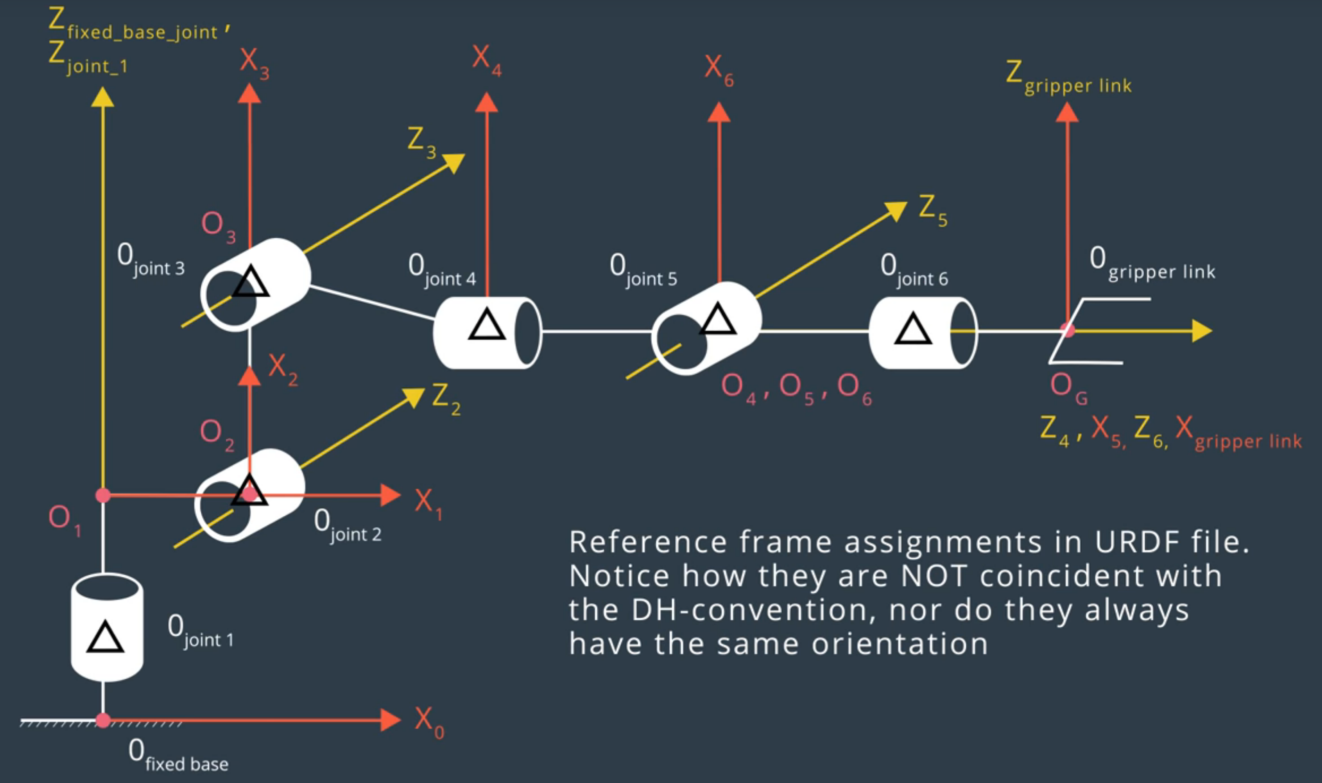
This project is using the Kuka KR 210 robotic arm which can be represented with the following list of joints (image credits: Udacity):
Based on comparison of the specifications we convert the robot dimension information to the DH table as follows:
DH = {
  alpha0: 0,      a0: 0,       theta1: theta1,         d1: 0.75,
  alpha1: -pi/2,  a1: 0.35,    theta2: theta2 - pi/2,  d2: 0,
  alpha2: 0,      a2: 1.25,    theta3: theta3,         d3: 0,
  alpha3: -pi/2,  a3: -0.054,  theta4: theta4,         d4: 1.5,
  alpha4: pi/2,   a4: 0,       theta5: theta5,         d5: 0,
  alpha5: -pi/2,  a5: 0,       theta6: theta6,         d6: 0,
  alpha6: 0,      a6: 0,       theta7: 0,              d7: 0.303,
}
Since all the joints are revolute it is only the theta parameters which can vary.
The transformation matrices can be calculated as follows:
def GetRotationMatrixByDHParams(alpha, a, q, d):
    return Matrix([[cos(q),             -sin(q),               0.0,         a],
                   [sin(q) * cos(alpha), cos(q) * cos(alpha), -sin(alpha), -sin(alpha) * d],
                   [sin(q) * sin(alpha), cos(q) * sin(alpha),  cos(alpha),  cos(alpha) * d],
                   [0.0,                 0.0,                  0.0,         1.0]])

T0_1 = GetRotationMatrixByDHParams(alpha0, a0, q1, d1).subs(DH)
T1_2 = GetRotationMatrixByDHParams(alpha1, a1, q2, d2).subs(DH)
T2_3 = GetRotationMatrixByDHParams(alpha2, a2, q3, d3).subs(DH)
T3_4 = GetRotationMatrixByDHParams(alpha3, a3, q4, d4).subs(DH)
T4_5 = GetRotationMatrixByDHParams(alpha4, a4, q5, d5).subs(DH)
T5_6 = GetRotationMatrixByDHParams(alpha5, a5, q6, d6).subs(DH)
T6_7 = GetRotationMatrixByDHParams(alpha6, a6, q7, d7).subs(DH)
The resulting transofrmations for each joint would be: T0_1:
Matrix([
[cos(q1), -sin(q1), 0.0,    0],
[sin(q1),  cos(q1),   0,    0],
[      0,        0,   1, 0.75],
[    0.0,      0.0, 0.0,  1.0]])
T1_2:
Matrix([
[sin(q2),  cos(q2), 0.0, 0.35],
[      0,        0,   1,    0],
[cos(q2), -sin(q2),   0,    0],
[    0.0,      0.0, 0.0,  1.0]])
T2_3:
Matrix([
[cos(q3), -sin(q3), 0.0, 1.25],
[sin(q3),  cos(q3),   0,    0],
[      0,        0,   1,    0],
[    0.0,      0.0, 0.0,  1.0]])
T3_4:
Matrix([
[ cos(q4), -sin(q4), 0.0, -0.054],
[       0,        0,   1,    1.5],
[-sin(q4), -cos(q4),   0,      0],
[     0.0,      0.0, 0.0,    1.0]])
T4_5:
Matrix([
[cos(q5), -sin(q5), 0.0,   0],
[      0,        0,  -1,   0],
[sin(q5),  cos(q5),   0,   0],
[    0.0,      0.0, 0.0, 1.0]])
T5_6:
Matrix([
[ cos(q6), -sin(q6), 0.0,   0],
[       0,        0,   1,   0],
[-sin(q6), -cos(q6),   0,   0],
[     0.0,      0.0, 0.0, 1.0]])
T6_7 (End Effector):
Matrix([
[  1,   0, 0.0,     0],
[  0,   1,   0,     0],
[  0,   0,   1, 0.303],
[0.0, 0.0, 0.0,   1.0]])
The full transformation thous is the following:
T0_EE = T0_1 * T1_2 * T2_3 * T3_4 * T4_5 * T5_6 * T6_7
Which results in the following matrix:
simplify(T0_EE) = Matrix([
[((sin(q1)*sin(q4) + sin(q2 + q3)*cos(q1)*cos(q4))*cos(q5) + sin(q5)*cos(q1)*cos(q2 + q3))*cos(q6) - (-sin(q1)*cos(q4) + sin(q4)*sin(q2 + q3)*cos(q1))*sin(q6), -((sin(q1)*sin(q4) + sin(q2 + q3)*cos(q1)*cos(q4))*cos(q5) + sin(q5)*cos(q1)*cos(q2 + q3))*sin(q6) + (sin(q1)*cos(q4) - sin(q4)*sin(q2 + q3)*cos(q1))*cos(q6), -(sin(q1)*sin(q4) + sin(q2 + q3)*cos(q1)*cos(q4))*sin(q5) + cos(q1)*cos(q5)*cos(q2 + q3), -0.303*sin(q1)*sin(q4)*sin(q5) + 1.25*sin(q2)*cos(q1) - 0.303*sin(q5)*sin(q2 + q3)*cos(q1)*cos(q4) - 0.054*sin(q2 + q3)*cos(q1) + 0.303*cos(q1)*cos(q5)*cos(q2 + q3) + 1.5*cos(q1)*cos(q2 + q3) + 0.35*cos(q1)],
[ ((sin(q1)*sin(q2 + q3)*cos(q4) - sin(q4)*cos(q1))*cos(q5) + sin(q1)*sin(q5)*cos(q2 + q3))*cos(q6) - (sin(q1)*sin(q4)*sin(q2 + q3) + cos(q1)*cos(q4))*sin(q6), -((sin(q1)*sin(q2 + q3)*cos(q4) - sin(q4)*cos(q1))*cos(q5) + sin(q1)*sin(q5)*cos(q2 + q3))*sin(q6) - (sin(q1)*sin(q4)*sin(q2 + q3) + cos(q1)*cos(q4))*cos(q6), -(sin(q1)*sin(q2 + q3)*cos(q4) - sin(q4)*cos(q1))*sin(q5) + sin(q1)*cos(q5)*cos(q2 + q3),  1.25*sin(q1)*sin(q2) - 0.303*sin(q1)*sin(q5)*sin(q2 + q3)*cos(q4) - 0.054*sin(q1)*sin(q2 + q3) + 0.303*sin(q1)*cos(q5)*cos(q2 + q3) + 1.5*sin(q1)*cos(q2 + q3) + 0.35*sin(q1) + 0.303*sin(q4)*sin(q5)*cos(q1)],
[                                                                -(sin(q5)*sin(q2 + q3) - cos(q4)*cos(q5)*cos(q2 + q3))*cos(q6) - sin(q4)*sin(q6)*cos(q2 + q3),                                                                  (sin(q5)*sin(q2 + q3) - cos(q4)*cos(q5)*cos(q2 + q3))*sin(q6) - sin(q4)*cos(q6)*cos(q2 + q3),                                     -sin(q5)*cos(q4)*cos(q2 + q3) - sin(q2 + q3)*cos(q5),                                                                                 -0.303*sin(q5)*cos(q4)*cos(q2 + q3) - 0.303*sin(q2 + q3)*cos(q5) - 1.5*sin(q2 + q3) + 1.25*cos(q2) - 0.054*cos(q2 + q3) + 0.75],
[                                                                                                                                                            0,                                                                                                                                                             0,                                                                                        0,                                                                                                                                                                                                            1.0]])
We have position and orientation of the end-effector:
px = req.poses[x].position.x
py = req.poses[x].position.y
pz = req.poses[x].position.z

(roll, pitch, yaw) = tf.transformations.euler_from_quaternion(
    [req.poses[x].orientation.x, req.poses[x].orientation.y,
        req.poses[x].orientation.z, req.poses[x].orientation.w])
From the position and orientation of the end-effector we can find position of the wrist:
EE_orientation_corrected_subs = EE_orientation_corrected.subs({'r': roll, 'p': pitch, 'y': yaw})
WC_pos = EE_pos - DH[d7] * EE_orientation_corrected_subs[:, 2]
Theta1 can be found as:
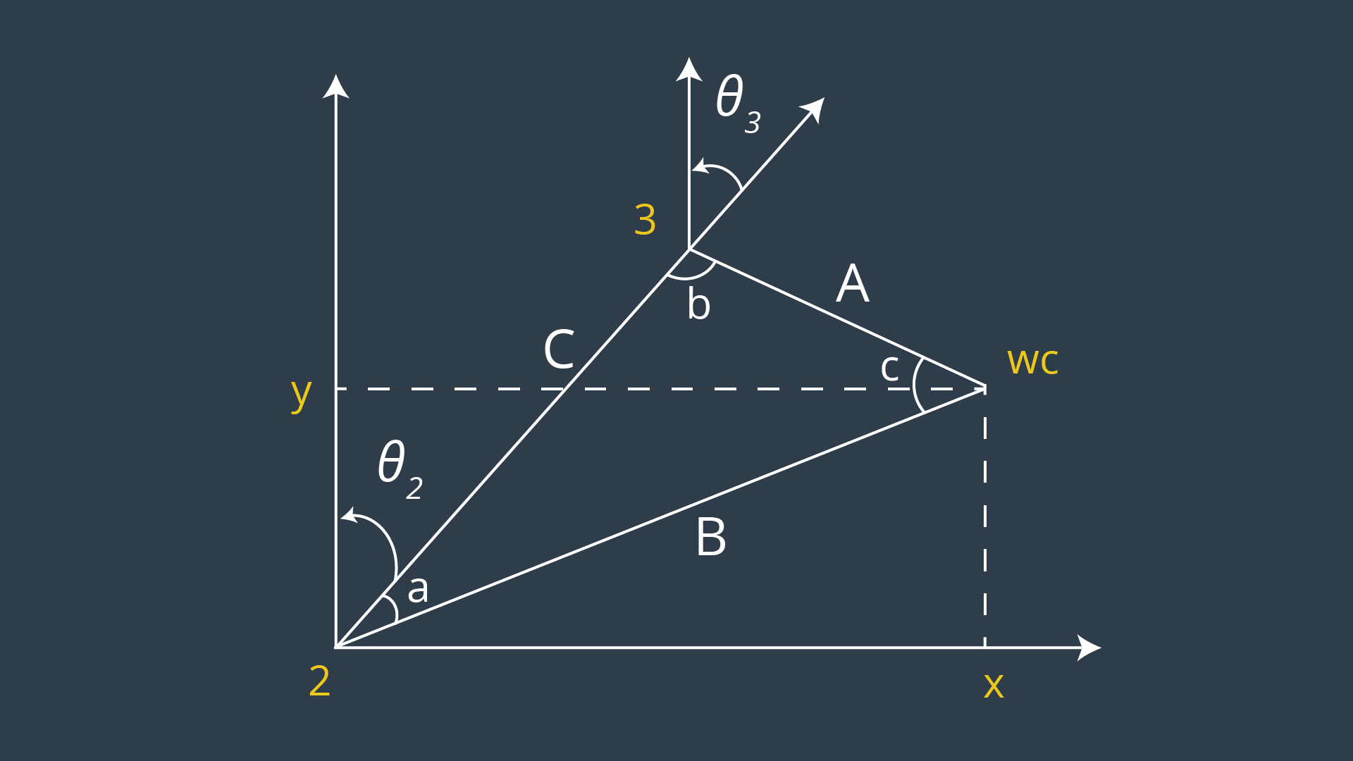
theta1 = atan2(WC_pos[1], WC_pos[0])Then from this image and trigonometry we can find theta2 and theta3:
s1 = DH[d4]
s2 = sqrt(pow(sqrt(WC_pos[0] * WC_pos[0] + WC_pos[1] * WC_pos[1]) - DH[a1], 2) + pow((WC_pos[2] - DH[d1]), 2))
s3 = DH[a2]

angle1 = acos((s2 * s2 + s3 * s3 - s1 * s1) / (2 * s2 * s3))
angle2 = acos((s1 * s1 + s3 * s3 - s2 * s2) / (2 * s1 * s3))
angle3 = acos((s1 * s1 + s2 * s2 - s3 * s3 ) / (2 * s1 * s2))

theta2 = pi/2. - angle1 - atan2(WC_pos[2] - DH[d1], sqrt(WC_pos[0] * WC_pos[0] + WC_pos[1] * WC_pos[1]) - DH[a1])
theta3 = pi/2. - (angle2 + atan2(math.abs(DH[a3]), math.abs(DH[d4]))
Once we have thetas 1-3 we can calculate transformation from the joint 0 to the joint 3:
R0_3 = T0_1[0:3,0:3] * T1_2[0:3,0:3] * T2_3[0:3,0:3]
R0_3 = R0_3.evalf(subs={q1: theta1, q2:theta2, q3: theta3})
Then we can find transformation from joints 3 to 6 by using the inverse of R0_3:
R3_6 = R0_3.transpose() * EE_orientation_corrected_subsAnd finally extract the remaining thetas 3-6 from this matrix:
theta4 = atan2(R3_6[2,2], -R3_6[0,2])
theta5 = atan2(sqrt(R3_6[0,2]*R3_6[0,2] + R3_6[2,2]*R3_6[2,2]), R3_6[1,2])
theta6 = atan2(-R3_6[1,1], R3_6[1,0]) 

