- Šimon Roubal
- Petr Medek
- Jakub Socha
- Ondřej Ryšavý
Link to this file in your GitHub repository:
https://github.com/Simon-Roubal/Meteo-station
The goal of the project is to develop a weather station with 2-axis solar panel tracking using various sensors and servos. The project will be based on an Arduino UNO board with an Atmega328p microcontroller and written in C language.
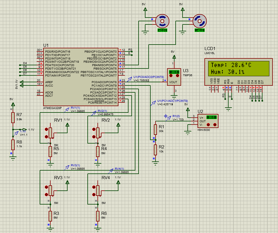
The basic of the whole hardware is the Arduino UNO board with an Atmega328p microcontroller. Three types of sensors are connected to this board. Temperature sensor TMP36, humidity sensor HIH5030 and four pieces of photoresistors. There are also two servo motors that serve in combination with photoresistors to move a solar panel and follow the sun. For showing information about temperature and humidity is here LCD display LM016L.
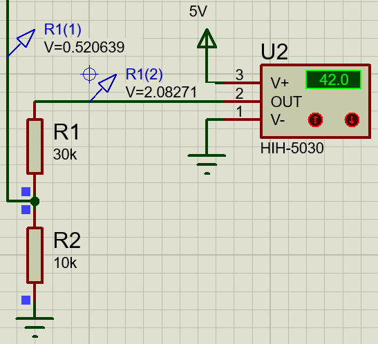
HIH5030 is connected to the board through a voltage divider because of output voltage would not be higher than a reference voltage. (1.1V).
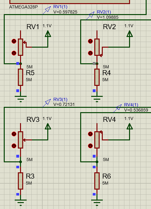
The function of moving solar panel works on the principle four photo elements (in our case photoresistors), which are separated with some light barrier. Photoresistors are connected in a voltage divider. The output voltage of this divider says how much light intensity is on photoresistors at the moment. If the voltage on every photoresistor, with some deviation, is the same then is panel turned to the sun.
Condition for the first installation: In the first installation user must turn the panel to the sun.
In the case of simulation, the photoresistors were replaced by potentiometers.
Principle of solar sensor in practice: https://www.youtube.com/watch?v=_6QIutZfsFs
Two of the libraries were used for DE2 laboratory lessons: https://github.com/tomas-fryza/Digital-electronics-2/tree/master/Labs/library
| Function | Description |
|---|---|
| lcd | Peter Fleury's LCD library |
| timer | Timer library for AVR-GCC we made during laboratories |
| pwm_servo | Our library for controling PWM servos |
We had to make a separate PWM servo library with funcion for each position, bacause compiler will accept implut for _delay_ms() as a constant. So we solved the problem this way.
| Function | Description |
|---|---|
servo_turn_to_postion |
Move to position specified by given attribute |
servo_move_plus_ninety |
Move to +90° |
servo_move_plus_eighty |
Move to +80° |
servo_move_plus_seventy |
Move to +70° |
servo_move_plus_sixty |
Move to +60° |
servo_move_plus_fifty |
Move to +50° |
servo_move_plus_fourty |
Move to +40° |
servo_move_plus_thirty |
Move to +30° |
servo_move_plus_twenty |
Move to +20° |
servo_move_plus_ten |
Move to +10° |
servo_move_zero |
Move to 0° |
servo_move_minus_ten |
Move to -10° |
servo_move_minus_twenty |
Move to -20° |
servo_move_minus_thirty |
Move to -30° |
servo_move_minus_fourty |
Move to -40° |
servo_move_mimus_fifty |
Move to -50° |
servo_move_minus_sixty |
Move to -60° |
servo_move_minus_seventy |
Move to -70° |
servo_move_minus_eighty |
Move to -80° |
servo_move_minus_ninety |
Move to -90° |
Example of function for +90°:
void servo_move_plus_ninety(volatile uint8_t *reg_name, volatile uint8_t *port_name, uint8_t pin_num)
{
	uint16_t x = 1250;                         //pulse width
	uint16_t y = 20000-x;                      //the difference between the period and the pulse width
	*reg_name = *reg_name | (1<<pin_num);
	*port_name = *port_name & ~(1<<pin_num);
	*port_name = *port_name |(1<<pin_num);
	_delay_us(x);
	*port_name = *port_name & ~(1<<pin_num);
	_delay_us(y);
}
The value of variable x is the value of pulse width which controls rotation level.
Firstly in the main function there is incitialization of LCD and positioning servos to default position. Then default LCD strings are diplayes and the custom symbols for LCD are loaded to memory and displayed too. Next we configure ADC and interrupts
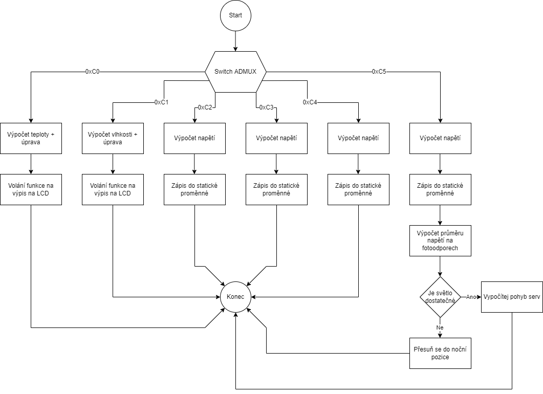
IRS for timer one contains only one line which is execuion of ADC conversion on preselected port and is called every 262ms.
This interrupt rutine for ADC contains switch which serves as multiplex for ADC pins. So each time function is called it reads different ADC pin shifted by one from previous. In cases for thermal and humidity sensors there is conversion to desired unit and calling of appropriate function for displaying on LCD. In cases for photoresistors there is allways ADC value converted to voltage and saved to static variable. In last photoresistor case there is also a conditon for deciding if there is enough light to calculate servo movements of to go to night position and be ready for next day.
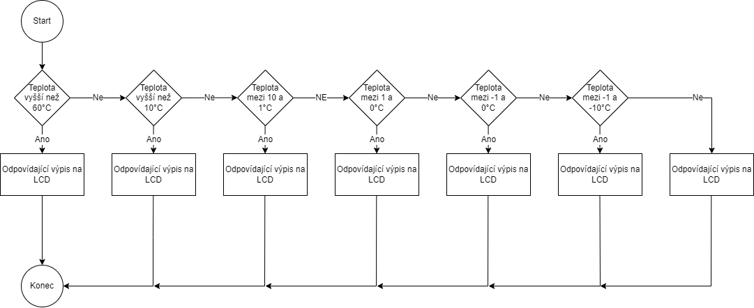
This function correctly displays measured temperature by its value
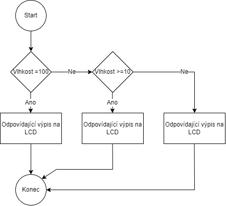
This function correctly displays measured humidity by its value
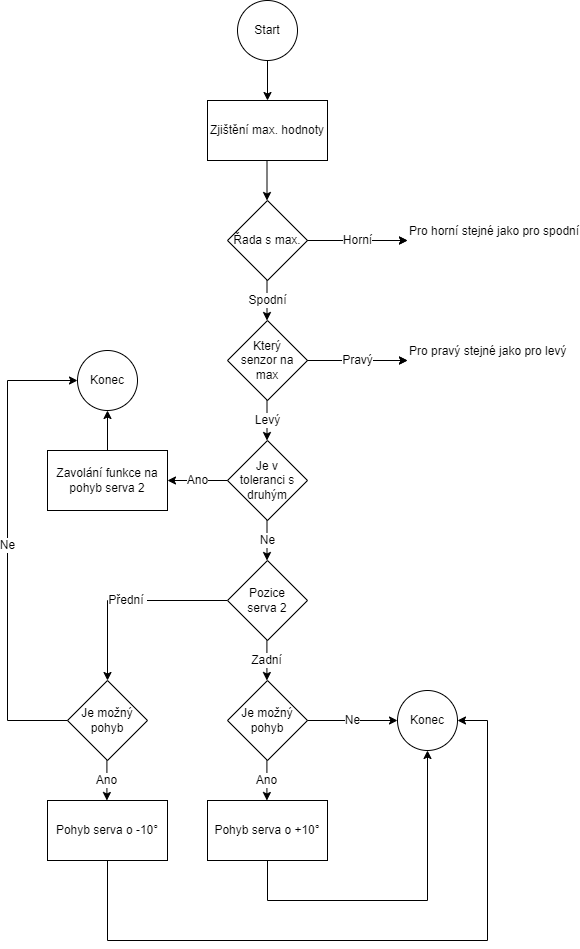
First of two functions for calculating servo movement. Firstly it determines which sensor has the highest light shining on it and if it is located in top or bottom row of sensors. According to that it calculates allowed match toleration of 90% and compares the value of sensor with highest light on it with corresponding sensor in the same row. If it's whitin toleration it proceeds to calculating movement of next servo. If not it tursn servo by 10 degrees if possible. Same goes for all possible combinations.
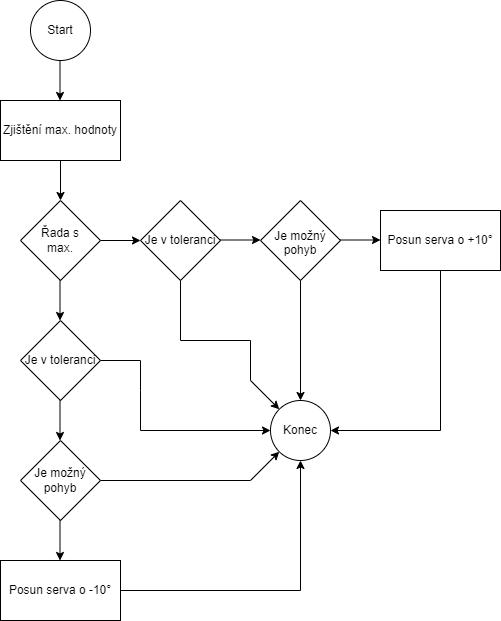
This function also get's the highest value, but this time only averaged rows are compared. then it works in simillar way than the previous function.
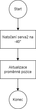
Function that moves second servo to starting position to be ready for next day while keeping same postion for servo 1.
Moves the solar pannel to default position.
[1] Base for timer library: https://github.com/tomas-fryza/Digital-electronics-2/tree/master/Labs/library
[2] LCD library: http://www.peterfleury.epizy.com/doxygen/avr-gcc-libraries/group__pfleury__lcd.html
[3] TMP36: https://www.analog.com/media/en/technical-documentation/data-sheets/TMP35_36_37.pdf
[4] HIH5030: https://sensing.honeywell.com/honeywell-sensing-hih5030-5031-series-product-sheet-009050-2-en.pdf
[5] Photoresistors: https://dratek.cz/arduino/1073-fotorezistor-5mm-gl5539.html
[6] LM016L: https://www.datasheet-pdf.info/entry/LM016L
[7] Principle of solar sensor in practice: https://www.youtube.com/watch?v=_6QIutZfsFs
