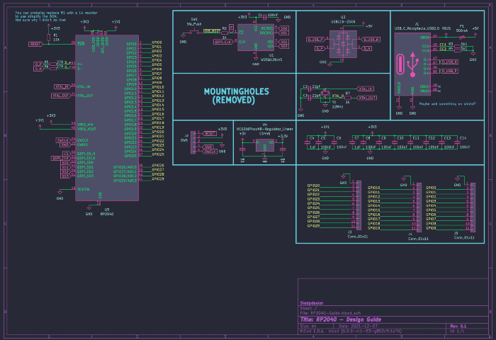
This guide requires you to have prerequisite knowledge about PCB design and a little about the RP2040. This is not a guide for absolute beginners and should not be treated as one.
I have multiple tested and working boards using the RP2040, including an open source one you can find here!
Bit of a disclaimer: I have mostly switched from RP2040 over to STM32F072 due to a few reasons. Mostly component cost and the amount of parts necessary, as well as overall stability. I have a tested and OSH f072 PCBs available on github. Namely here, here, and here. Designing with f072 is generally easier as well, so I would suggest it even for beginners.
To open these files, you will need a recent stable version of KiCad (6.0 or later).
Stop using KiCad 5.X, it's out of date
You can either import them into your own library or keep them separate.
- Symbol:
- Created by me to be easier to use
/PCB/Libraries/Sleep-lib
- Footprint:
- Taken from Raspberry
/PCB/Libraries/Footprints/RP2040-QFN-56.kicad_mod- 3D Model is included
Images of the 3DView, EEschema, and PCBNew in the /img folder.
All the other information I found about the chip is in in the /Pico-Resources Folder
THIS IMAGE WILL BE OUT OF DATE. LOOK AT THE PDF FOR THE LATEST VERSION.

If you want to know more about the components choices, read the section below or Raspberry's hardware design example.
The PDF is /Pico-Resources/hardware-design-with-rp2040.pdf.
I would also recommend reading my Best practices for PCB Design guide before making your own schematic or PCB
Breakout for SWD/GPIO is NOT required.
Trust me on these pls
Use the XC6206, it's a basic part on JLC. The 200mA it provides is plenty for the RP2040.
The AMS1117 has high quiescent current, needs large caps, and has a bad minimum load. Don't use it.
C9002 is a great basic part for a 12MHz 3225 crystal
There are a ton of options for flash, but I tend to stick with C82317 as it's a basic part and has a good price. More than enough flash for any keyboard.
Although I didn't use a button on the included PCB files, you can easily add one yourself. A good cheap button that fits the Alps SKQG footprint is C318884.
THIS IMAGE WILL BE OUT OF DATE. LOOK AT THE KiCad FILES FOR THE LATEST VERSION.

- Fills inside of the MCU were taken from the design example. You can just copy paste them out. Make sure to set the correct zone priority and clearances. Zones are filled from high to low numbers.
- Keep the decoupling capacitors close to their respective pins.
- Keep the flash and crystal as close as possible to the MCU with minimal overlaps and vias
- If anything, just copy paste from my files
- I would suggest including an actual switch for USB BOOT or RESET on to make it easier to flash, but that's up to you.
- Everything on the PCB can be assembled by JLC, all the part numbers have been added to the components with the Kicad JLCPCB plugin
- I have tested and working JLC part numbers for all of the components, but check the stock levels and prices first before ordering. There may be a better alternative available
- There are a few different flash sizes and packages to choose from. All of them should work pretty much the same, since firmware size is not an issue. I usually just go with the cheapest option
Both QMK and Vial have support for RP2040 in their master branches. Make sure to check the features you want before designing
- QMK
- QMK Main Branch: https://github.com/qmk/qmk_firmware/
- RP2040 available features: https://docs.qmk.fm/#/platformdev_rp2040?id=raspberry-pi-rp2040
- Vial
- Vial Main Branch: https://github.com/vial-kb/vial-qmk/
- KMK
- Keyberon
To flash, hold the USB-BOOT button down as you plug in the keyboard (like Bootmagic reset)
You will need to install picotool with your distro's package manager of choice, or build it manually.
In order to be able to flash properly, you will need to configure a custom udev rule.
Open a terminal and execute this script.
sudo mkdir -p /etc/udev/rules.d/
echo '# /etc/udev/rules.d/99-pico.rules

# Make an RP2040 in BOOTSEL mode writable by all users, so you can `picotool`
# without `sudo`.
SUBSYSTEM=="usb", ATTRS{idVendor}=="2e8a", ATTRS{idProduct}=="0003", MODE="0666"

# Symlink an RP2040 running MicroPython from /dev/pico.
#
# Then you can `mpr connect $(realpath /dev/pico)`.
SUBSYSTEM=="tty", ATTRS{idVendor}=="2e8a", ATTRS{idProduct}=="0005", SYMLINK+="pico"", TAG+="uaccess", TAG+="udev-acl"' | sudo tee /etc/udev/rules.d/99-pico.rules
sudo udevadm control --reload-rules
sudo udevadm trigger
Command borrowed from xyz's VIAL docs
While the Raspberry Pi Pico RP2040 does not come with an EEPROM onboard, we simulate one by using a single 4K chunk of flash at the end of flash space.
Note that this is a simulated EEPROM and will only support the number of writes as the onboard flash chip, not the 100,000 or so of a real EEPROM. Therefore, do not frequently update the EEPROM or you may prematurely wear out the flash.
Source: https://arduino-pico.readthedocs.io/en/latest/eeprom.html
This isn't really an issue, as the flash chip I used is rated for 100k cycles link to datasheet
If all of this seems too daunting, my commissions are open! You can contact me on discord at Sleepdealer#0001 or through email at sleepdealer01@protonmail.com
Portfolio: https://sleepdealer.xyz/article/portfolio


