This library provides a Clojure(Script) wrapper over Emmett Lalish's incredible Manifold 3D geometry library. The CLJ implementation is based on JNI bindings to c++ produced via. javacpp: see https://github.com/SovereignShop/manifold. The CLJS implementation is based on emscripten build of Manifold for wasm.
It implements most of the library functionality, plus extends it to support polyhedrons and lofts. It provides nearly a full superset of OpenSCAD functionality.
Manifold represents a dramatic advance in the state-of-the-art of open-source programmatic CAD. It has been adopted by most major CAD kernels.
You need include the native Manifold Bindings for your platform separately. For example:
;; Linux
{:deps {org.clojars.cartesiantheatrics/manifold3d$linux-x86_64 {:mvn/version "1.0.73"}}}
;; Mac
{:deps {org.clojars.cartesiantheatrics/manifold3d$mac-x86_64 {:mvn/version "1.0.73"}}}
;; See build artifacts for experimental Windows jars: https://github.com/SovereignShop/manifold/actions
The Manifold .so libs are included in the bindings jar. You'll also need to have libassimp installed on your system:
;; Ubuntu
sudo apt install libassimp-dev
;; Mac
brew install pkg-config assimp
;; Windows
git clone https://github.com/assimp/assimp.git
cd assimp
git checkout v5.2.5
cmake CMakeLists.txt -DASSIMP_BUILD_ZLIB=ON -DCMAKE_BUILD_TYPE=Release
cmake --build . --config Release
cmake --install . --config Release
The ClojureScript lib is not yet well supported or available via. Maven. You'll have to clone the repo and move public/manifold.wasm into public/js/. Run npm install to install the gltf (for rendering meshes) then connect via. shadow. There's a half-baked function called createGLTF in manifold_viewer.js that will take a manifold and throw it onto the model-viewer element defined in the index.html.
See the core namespace for some documentation. Refer to the original library for more complete documentation.
Examples should look very familiar if you've ever used OpenSCAD.
(require '[clj-manifold3d.core
           :refer [cube cylinder sphere cylinder extrude cross-section frame square circle
                   union difference intersection translate get-mesh export-mesh status rotate
                   hull revolve offset refine smooth loft scale material text scale-to-height
                   three-point-arc frame-2d transform slice tetrahedron slices polyhedron]])


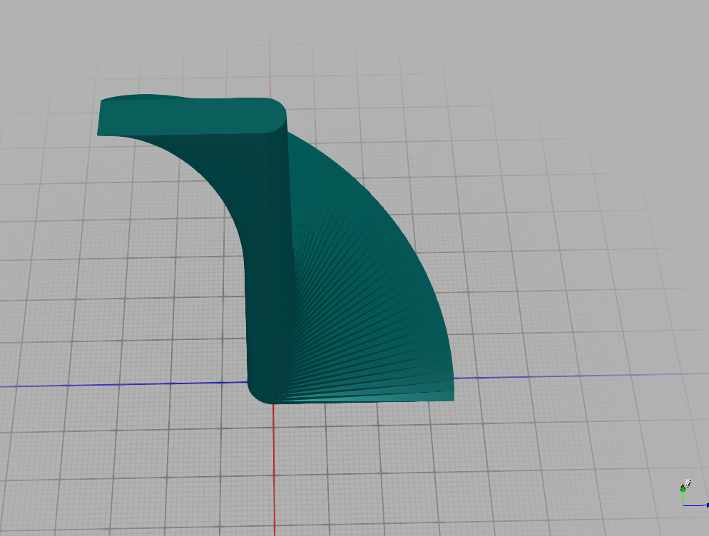
(-> (hull (circle 5)
          (-> (square 10 10 true)
              (translate [30 0])))
    (extrude 80 70 180 [0.7 0.7])
    (get-mesh)
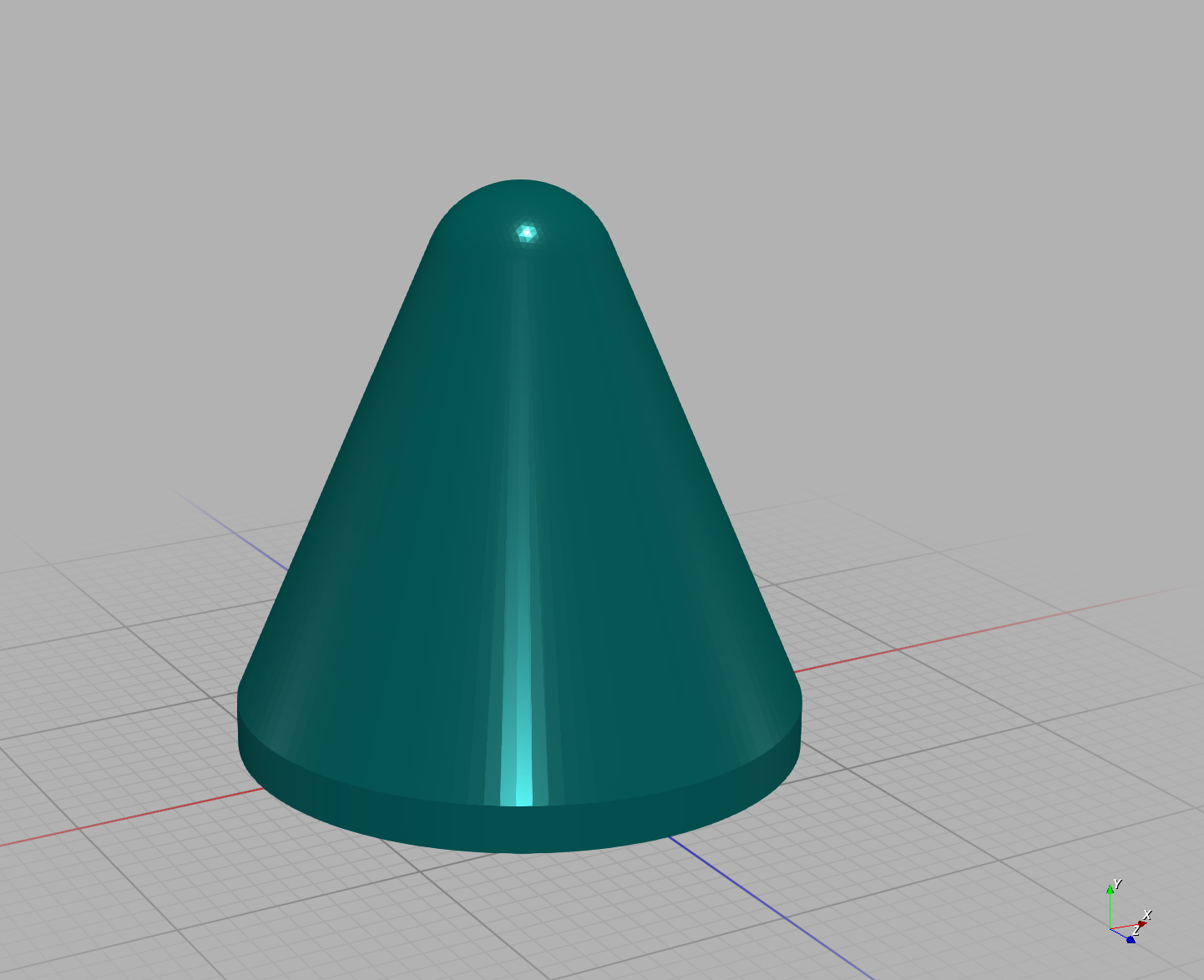
(export-mesh "hull2D.stl"))(-> (hull (cylinder 2 12 12 120)
(-> (sphere 4 120)
(translate [0 0 20])))
(get-mesh)
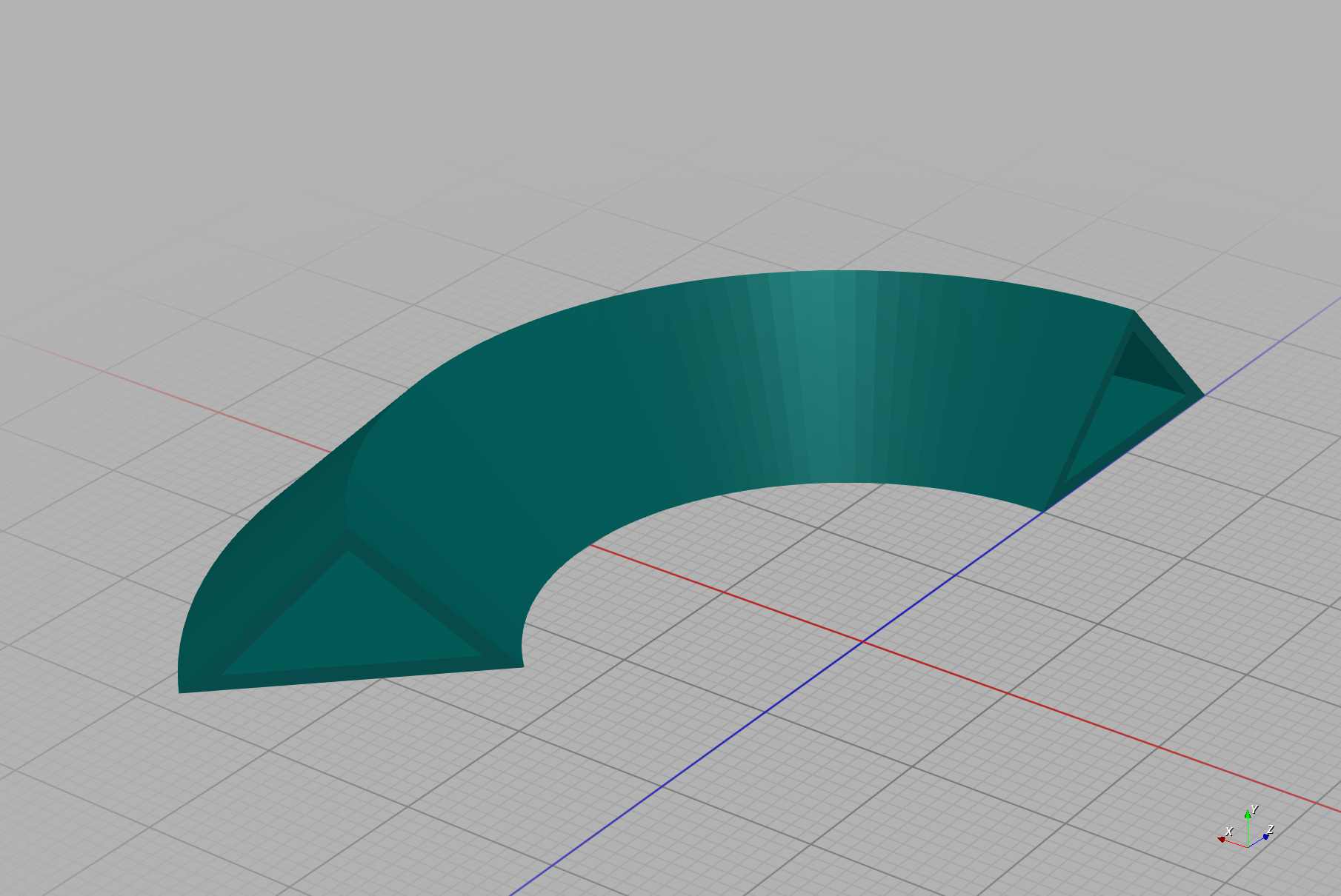
(export-mesh "hull3D.stl"))(let [m (-> (cross-section [[-10 0] [10 0] [0 10]])
(translate [30 0]))]
(-> (difference m (offset m -1))
(revolve 50 135)
(get-mesh)
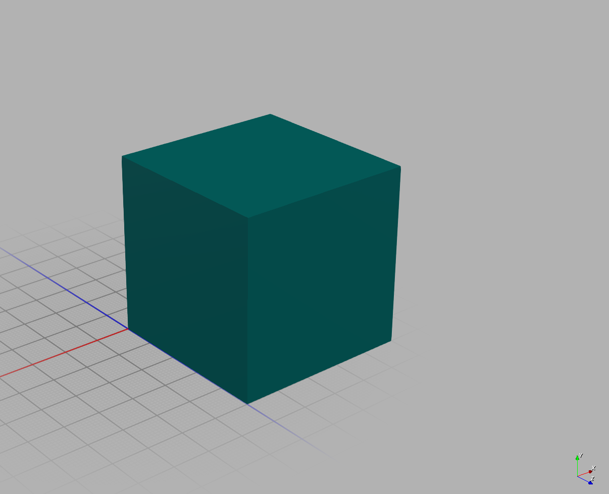
(export-mesh "revolve.stl")))(-> (polyhedron [[0 0 0]
[5 0 0]
[5 5 0]
[0 5 0]
[0 0 5]
[5 0 5]
[5 5 5]
[0 5 5]]
[[0 3 2 1]
[4 5 6 7]
[0 1 5 4]
[1 2 6 5]
[2 3 7 6]
[3 0 4 7]])
(get-mesh)
(export-mesh "polyhedron-cube.stl"))Transform frames, which are 4x3 affine transformation matrices, can be manipulated similar to manifolds.
(mapv vec
      (-> (frame 1)
          (translate [0 0 10])
          (vec)))
;; => [[1.0 0.0 0.0] [0.0 1.0 0.0] [0.0 0.0 1.0] [0.0 0.0 10.0]]
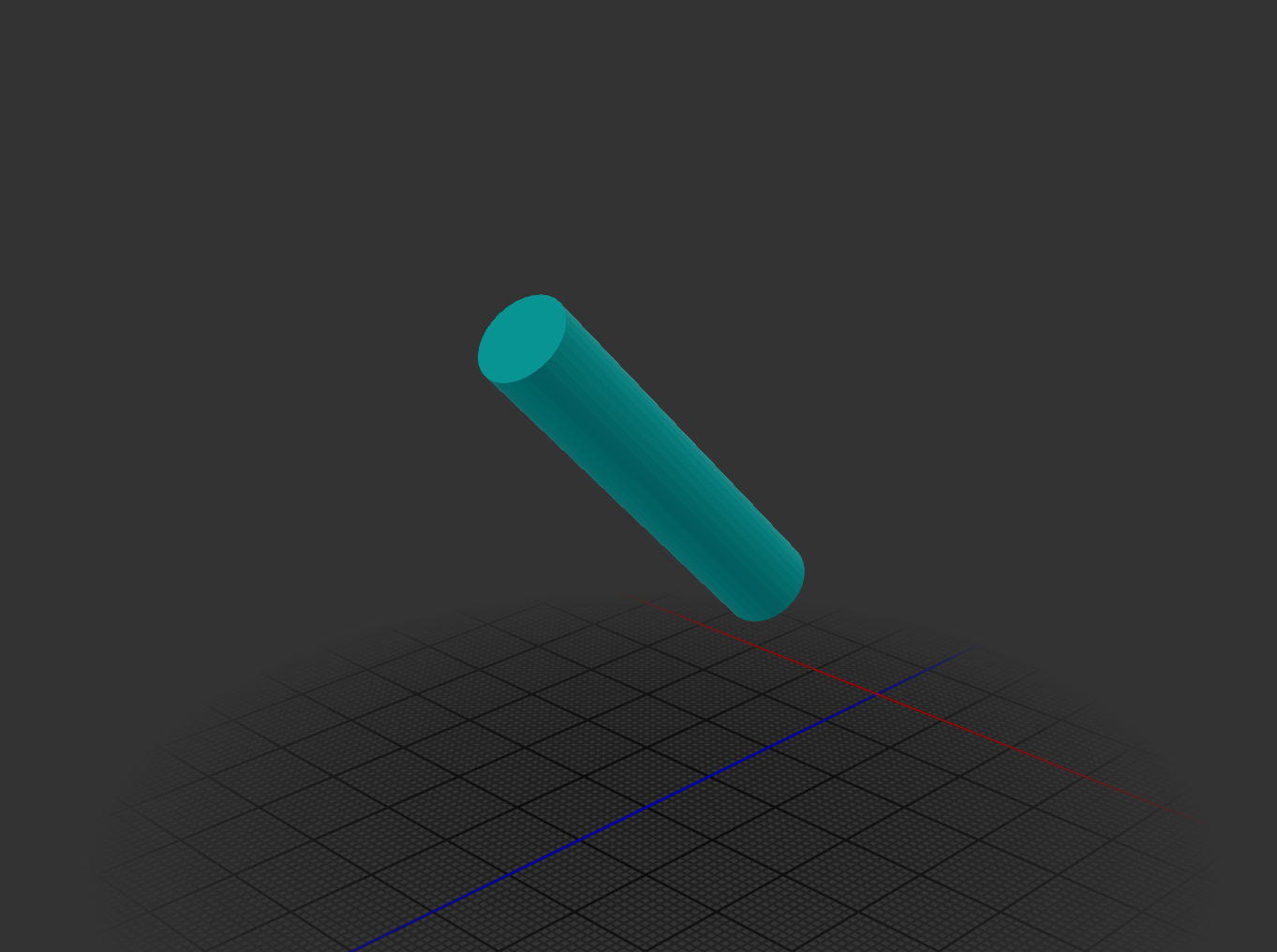
Frames transform slightly differently than manifolds. The rotation components are best thought of as basis vectors of a coordinate frame, with the last component representing the position of that frame. Rotations and translations are applied relative to the frame, turtle-graphics style. Here is an example of applying a transform to a cylinder:
(-> (cylinder 50 5)
    (transform (-> (frame 1)
                   (rotate [0 (/ Math/PI 4) 0])
                   (translate [0 0 30]))))
2D transform frames can also be manipulated similar to cross sections.
(mapv vec
      (-> (frame-2d 1)
          (translate [0 10])
          (vec)))
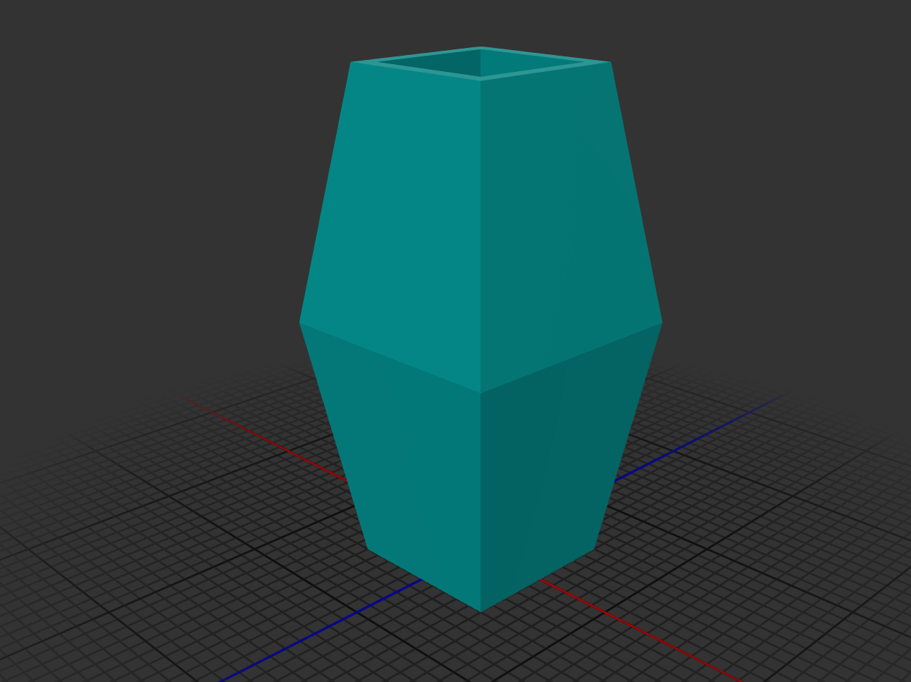
;; => [[1.0 0.0] [0.0 1.0] [0.0 0.0]](-> (let [c (difference (square 10 10 true) (square 8 8 true))]
(loft [c (scale c [1.5 1.5]) c]
[(frame 1)
(-> (frame 1) (translate [0 0 15]))
(-> (frame 1) (translate [0 0 30]))]))
(get-mesh)
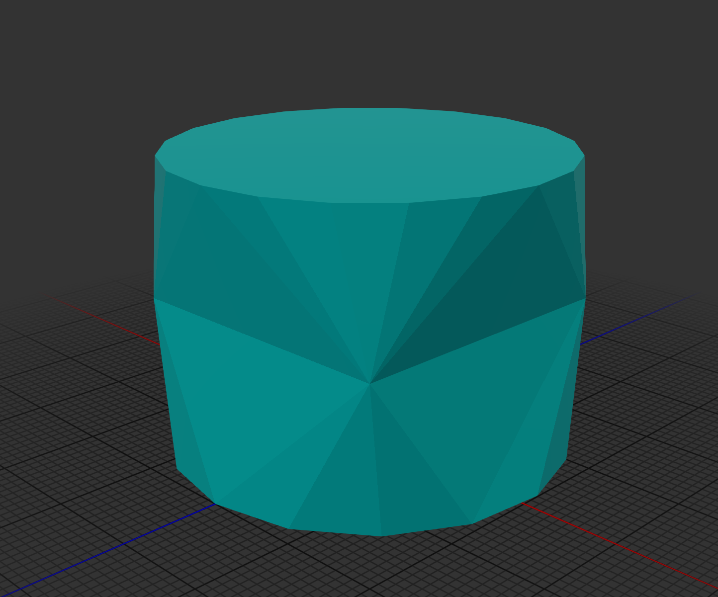
(export-mesh "loft.stl"))Loft and also handle one-to-many and many-to-one vertex mappings:
(-> (loft [(circle 20 15)
           (square 30 30 true)
           (circle 20 20)]
          [(frame 1)
           (-> (frame 1) (translate [0 0 15]))
           (-> (frame 1) (translate [0 0 30]))])
    (get-mesh)
    (export-mesh "monomorphic-loft.stl"))
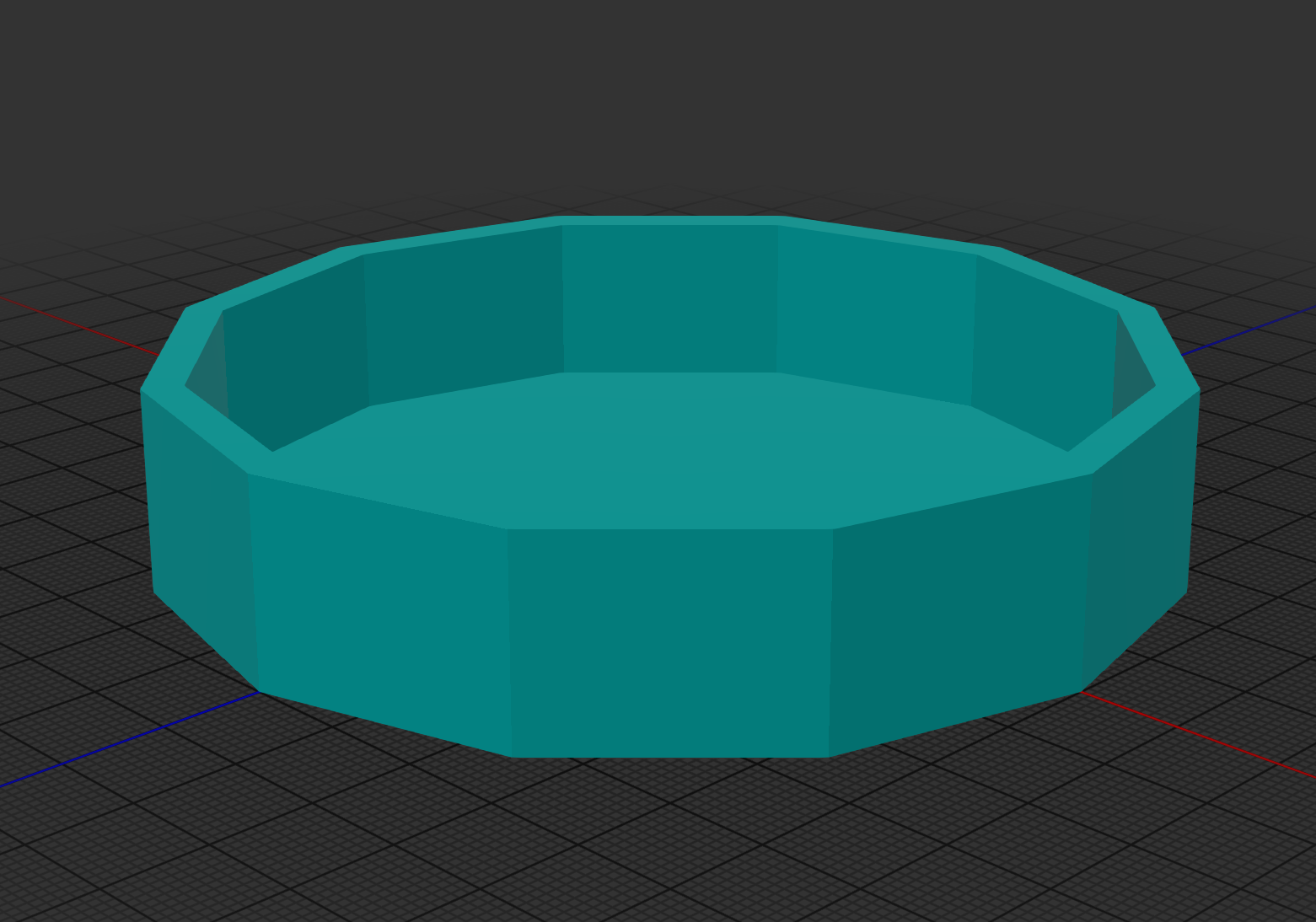
There is also a single arity version of loft:
(-> (loft [{:cross-section (circle 50 12)
            :frame (frame 1)}
           {:frame (-> (frame 1) (translate [0 0 20]))}
           {:frame (-> (frame 1) (translate [0 0 20]))
            :cross-section (circle 46 12)}
           {:frame (-> (frame 1) (translate [0 0 3]))}])
    (get-mesh)
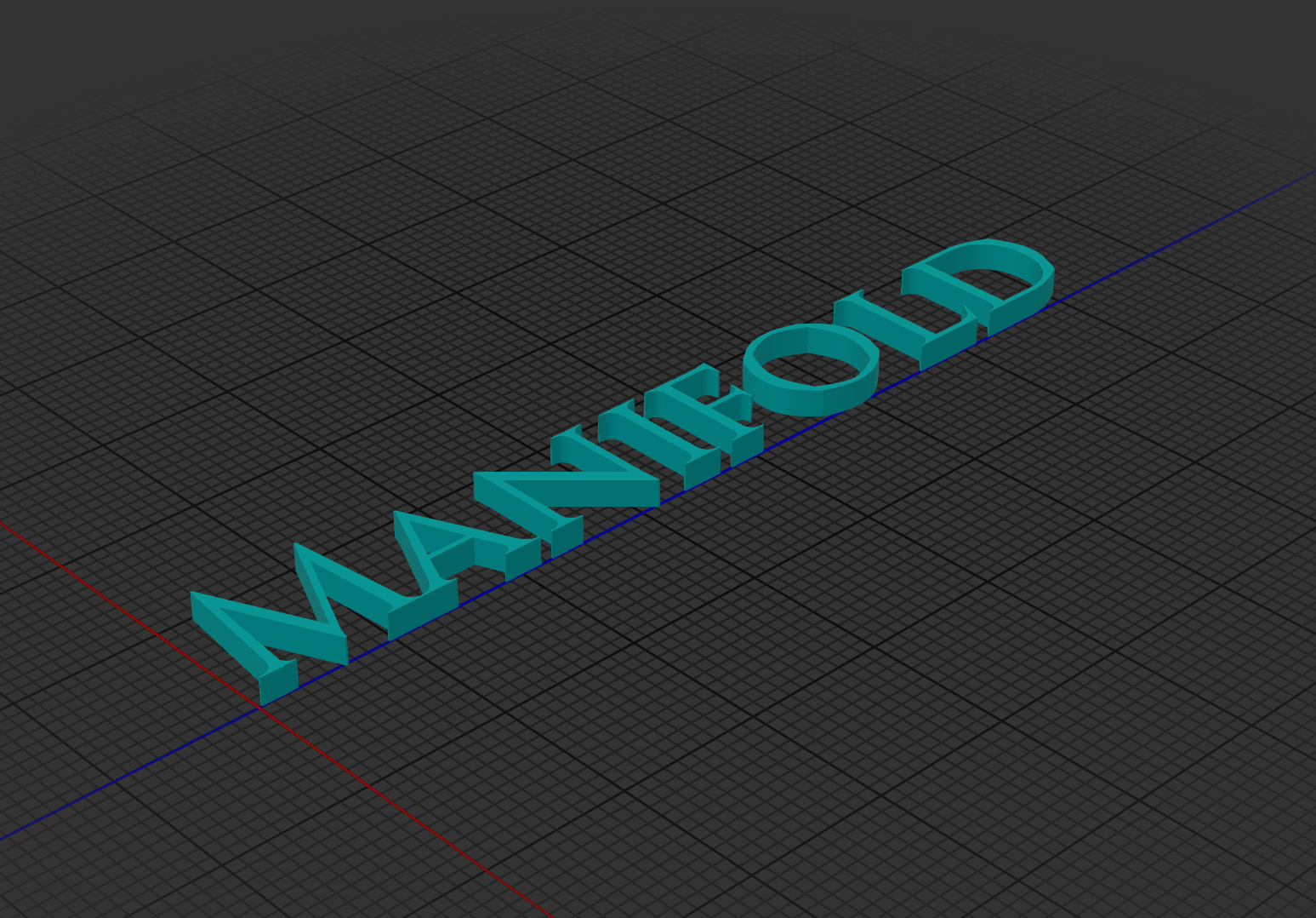
(export-mesh "single-arity-loft.stl"))(-> (text "resources/fonts/Cinzel-Regular.ttf" "Manifold" 10 20 :non-zero)
(scale-to-height 100)
(extrude 20)
(get-mesh)
(export-mesh "text.glb" :material mesh-material))Slice solves for the cross-section of a manifold that intersects the x/y plane.
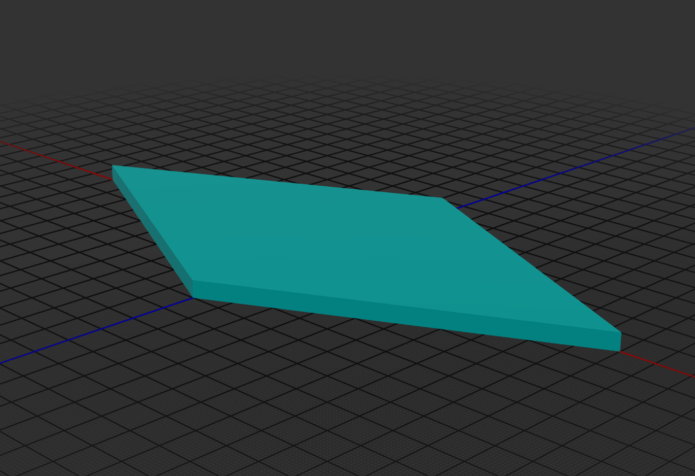
(-> (slice (scale (tetrahedron) [5 10 15]))
    (extrude 1/2)
    (get-mesh)
    (export-mesh "slice.glb" :material mesh-material))
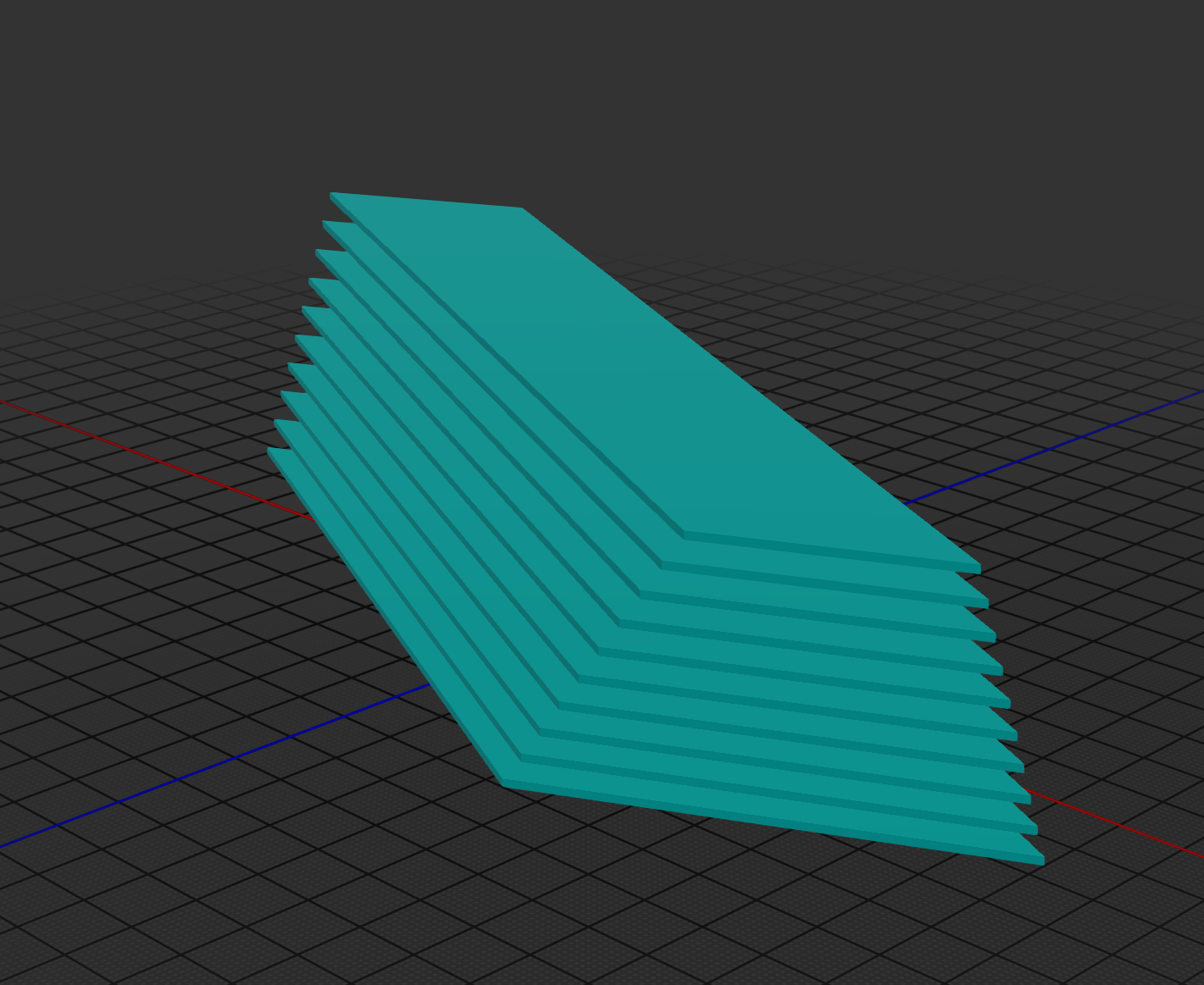
There is an efficient aglorithm that solves for N equally spaces slices.
(-> (union
     (for [[i slice] (map-indexed vector (slices (scale (tetrahedron) [5 10 15]) 5 10 10) )]
       (-> slice
           (extrude 1/8)
           (translate [0 0 (* i 0.5)]))))
    (get-mesh)
    (export-mesh "slices.glb" :material mesh-material))
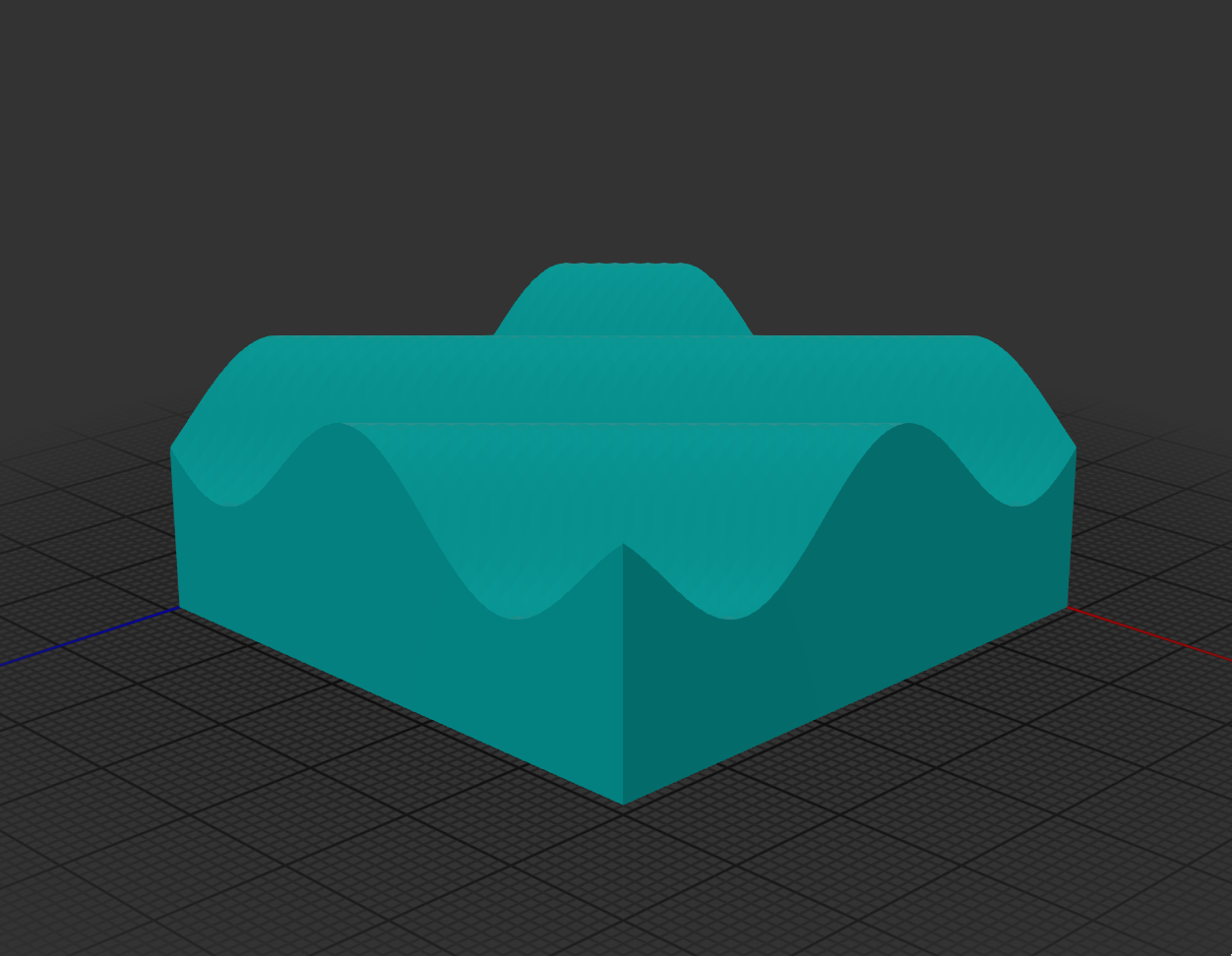
Surface creates a manifold from a heatmap structure:
(defn sinewave-heatmap
  "Generates a 3D sinewave heatmap.
  The output is a vector of vectors representing a square matrix.
  Each cell represents the height at that x/y coordinate based on a sinewave.

  Args:
  - size: The size of the matrix (width and height).
  - frequency: Frequency of the sinewave (controls the number of wave oscillations).
  - amplitude: Amplitude of the sinewave (controls the height of the wave).
  - phase: Phase shift of the sinewave.

  Returns a matrix where each value is the sinewave height at that coordinate."
  [size frequency amplitude phase]
  (vec
   (for [y (range size)]
     (vec
      (for [x (range size)]
        (+ (+ 10 amplitude)
           (* amplitude
              (Math/sin
               (+ (* frequency (/ x size))
                  (* frequency (/ y size))
                  phase)))))))))

(-> (sinewave-heatmap 50 10 5 0)
    (surface 1.0)
    (get-mesh)
    (export-mesh "sine-wave-surface.glb" :material mesh-material))
Use the underlying MeshUtils/CreateSurface for max performance when generating large heatmaps. You can also use create a surface from a .png, .jpg or other image file using load-surface.
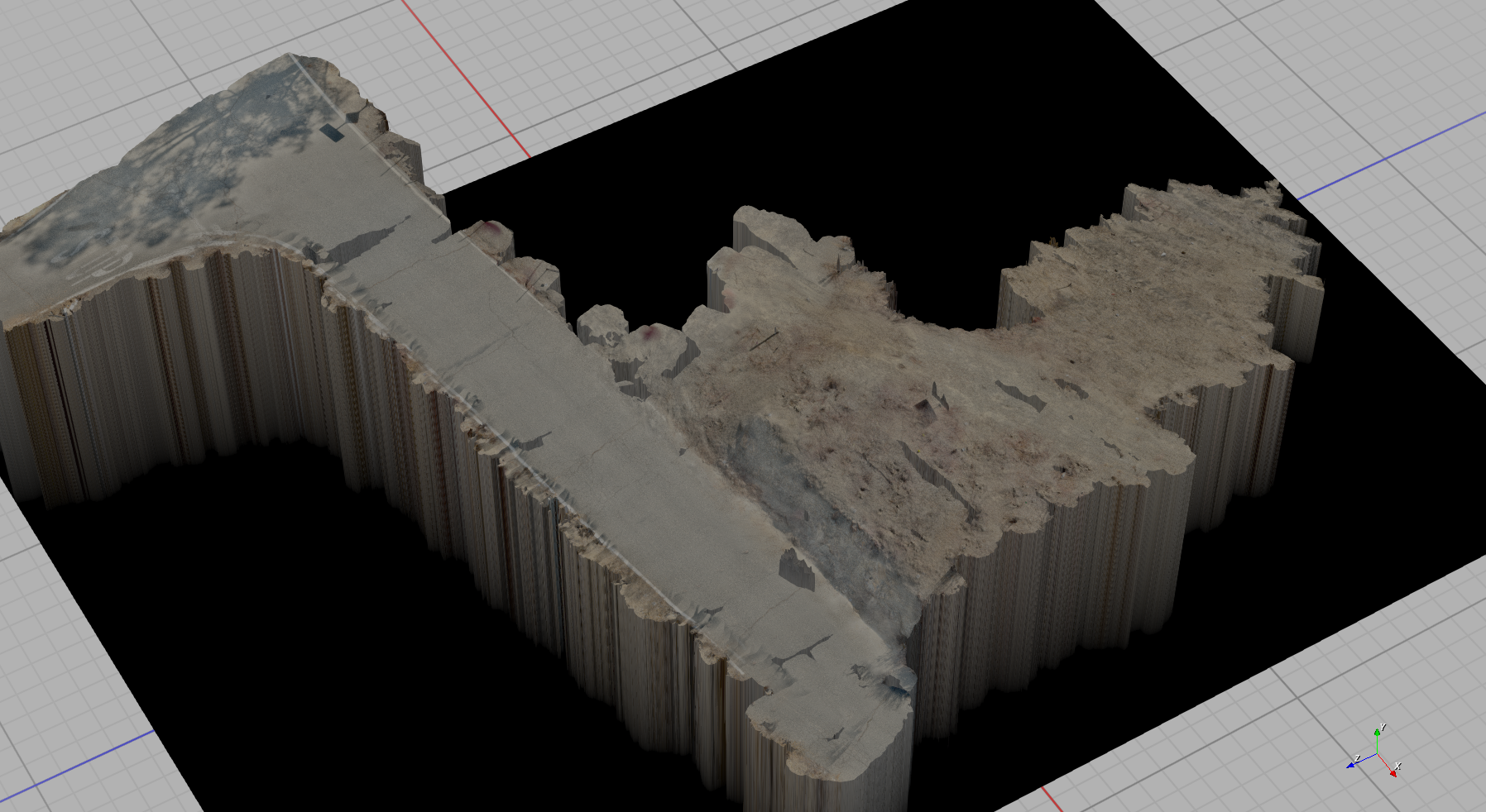
There is also a primitive algorithm to parse a .ply point cloud to a surface mesh, useful primarily for geo-mapping applications. Here's an example from a ~8GB point cloud:
Three point circle:
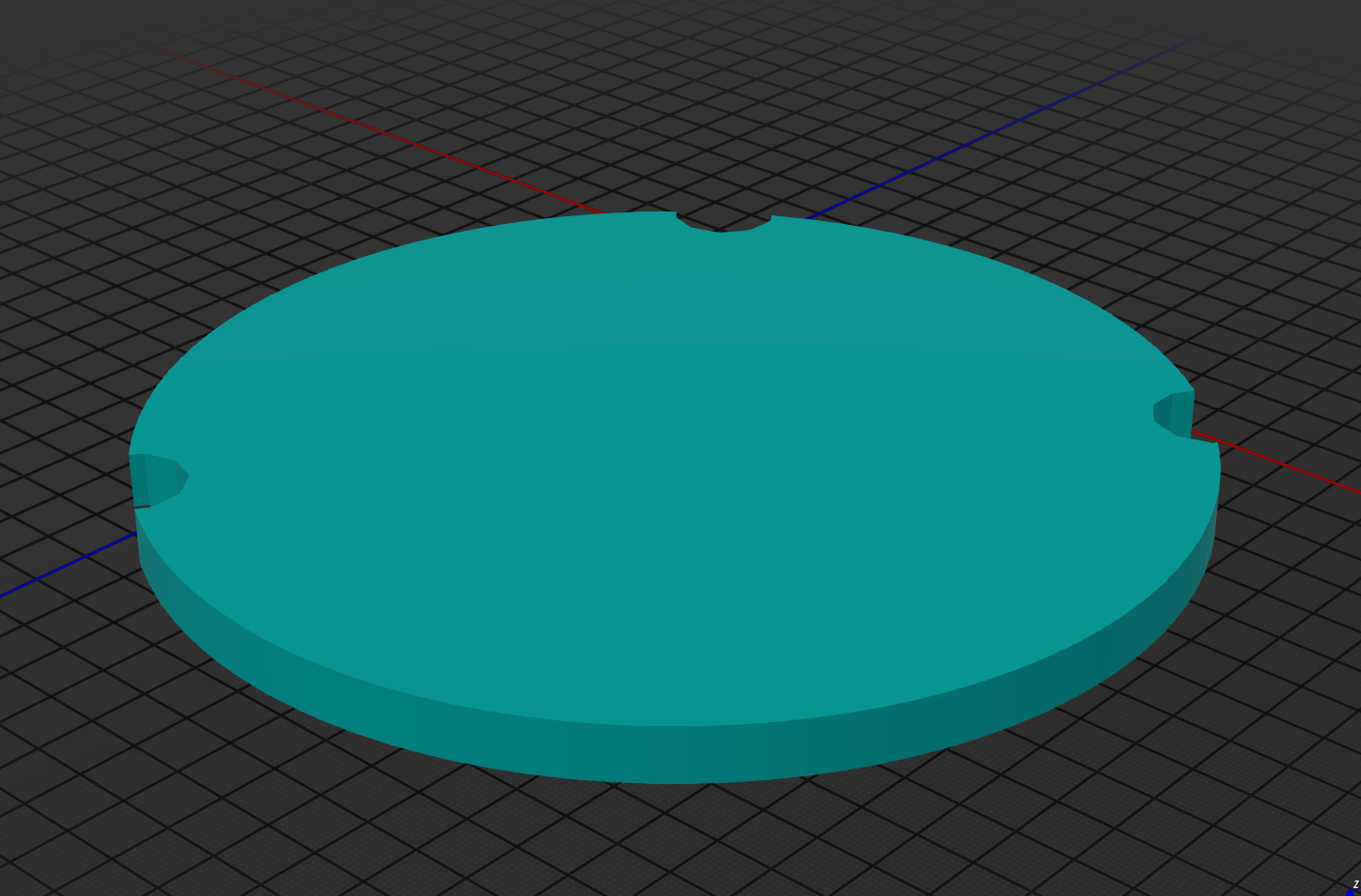
(let [p1 [0 0] p2 [1 12] p3 [15 0]]
  (-> (difference
       (circle p1 p2 p3 100)
       (union
        (for [p [p1 p2 p3]]
          (-> (circle 1 10)
              (translate p)))))
      (extrude 1)
      (get-mesh)
      (export-mesh "three-point-circle.glb" :material mesh-material)))
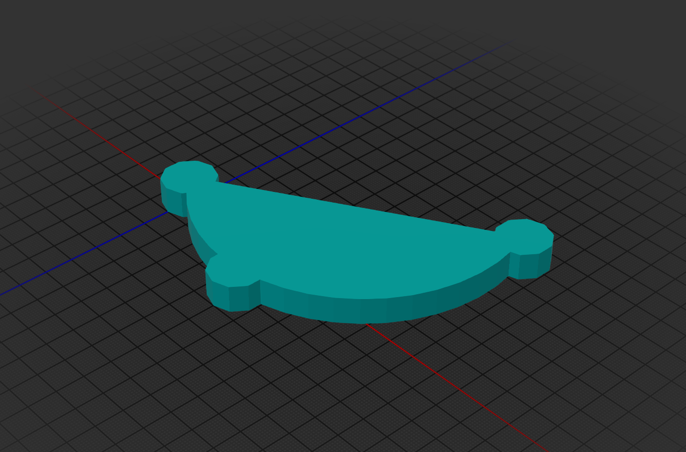
three point arc:
(let [p1 [0 0] p2 [2 5] p3 [-6 10]]
  (-> (union
       (three-point-arc p1 p2 p3 20)
       (union
        (for [p [p1 p2 p3]]
          (-> (circle 1 10)
              (translate p)))))
      (extrude 1)
      (get-mesh)
      (export-mesh "three-point-arc.glb" :material mesh-material)))
Use three-point-arc-points to get a vector of the points corresponding to the arc segment.
A Simple rapidly printable hydroponic tower: https://github.com/SovereignShop/spiralized-hydroponic-tower
Kossel delta printer: https://github.com/SovereignShop/kossel-printer/

