A 4-bit computer system for FPGAs. myco-fpga is a FPGA implementation of the MyCo (My little Computer) system, also known in German as TPS (Tastenprogrammierbare Steuerung).
With this system you can enter, run and edit programs with just three pushbuttons and 4 LEDs. The system also includes 4 digital inputs, typically connected to a array of DIP switches and a PWM output which can connect to an LED. This FPGA version does not have the two ADC channels that are available on the microcontroller version of MyCo/TPS. This feature will be added in the future.
To get you started, several demo programs are pre-loaded, selectable by the DIP switches. The demo programs can easily be modified or overwritten by your own programs.
A video showing a basic demonstration is available here
This is not a direct implementation of MyCo/TPS on an FPGA. It is a emulator, running on a pumpkin-cpu with a timer, pwm and IO peripherals. The assembly language source code for this emulator is in the file myco.asm. More information about the pumpkin-cpu core and be found here
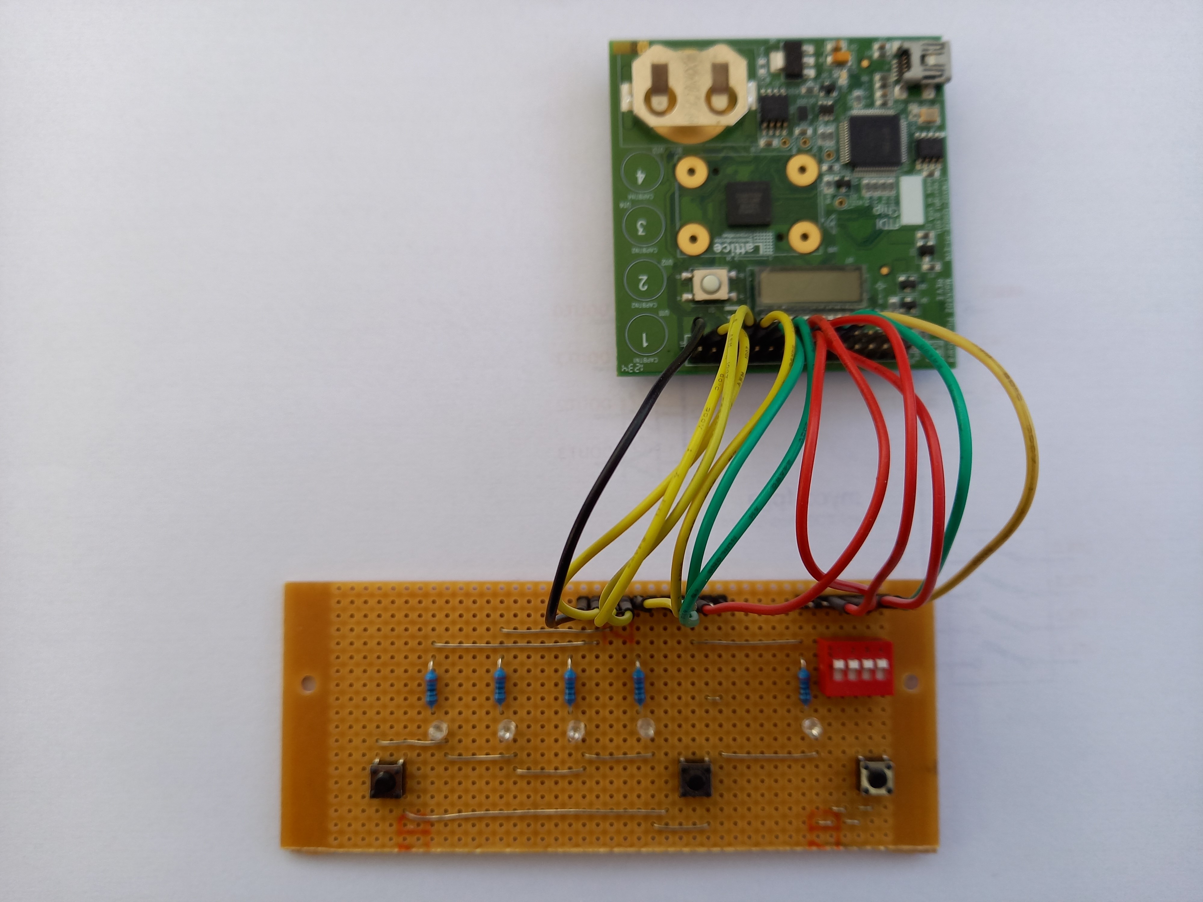
First you will need to find a FPGA evaluation board with at least 3 pushbuttons, 4 LEDS and a bank of 4 switches. The 4 switches are optional if you do not want to take advantage of the demo programs or experiment with the DIN port. I used a 'MachXO2 Pico Board' from Lattice Semiconductor connected to a small piece of stripboard with the switches and LEDS. This has an advantage of creating a layout that makes entering programs easier.
Create a project with your FPGA tool and add all these files, the lop-level module is myco.vhd
myco.vhd
myco_mem.vhd
pumpkin.vhd
timer.vhd
pwm.vhd
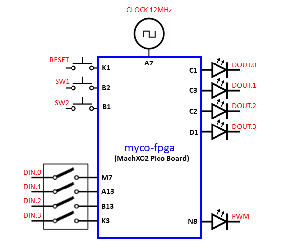
If you're using a Pico Board and Lattice Diamond, you can use the myco.lpf file which contains all the pin assignments shown in the diagram below. The switch inputs all have pull-ups enabled and expect to be pulled down when the switches are activated.
The block diagram shows the connections to the FPGA. This project should build on most FPGA tool chains. The code expects to be clocked at 12Mhz, different frequencies can be use by adjusting the timer and pwm clock division generics, refer to timer.vhd and pwm.vhd for further information.
The emulator is pre-assembled and stored in the file myco-mem.vhd. The source code myco.asm can be modified with a text editor and assembled using the PASM assembler. The PASM assembler is available here
Run this command to assemble the emulator.
pasm myco.asm 1024 myco_mem.vhd
A file myco_mem.vhd will be generated that can be use to replace the one in the FPGA project directory. You will then need to re-run the FPGA synthesis process.
- Instructions on how to program MyCo/TPS
- Information about the demo/default programs
- 2 Channel ADC
- Program storage in external EEPROM
Copyright (c) 2020 Steve Teal
Permission is hereby granted, free of charge, to any person obtaining a copy of this software and associated documentation files (the "Software"), to deal in the Software without restriction, including without limitation the rights to use, copy, modify, merge, publish, distribute, sublicense, and/or sell copies of the Software, and to permit persons to whom the Software is furnished to do so, subject to the following conditions:
The above copyright notice and this permission notice shall be included in all copies or substantial portions of the Software.
THE SOFTWARE IS PROVIDED "AS IS", WITHOUT WARRANTY OF ANY KIND, EXPRESS OR IMPLIED, INCLUDING BUT NOT LIMITED TO THE WARRANTIES OF MERCHANTABILITY, FITNESS FOR A PARTICULAR PURPOSE AND NONINFRINGEMENT. IN NO EVENT SHALL THE AUTHORS OR COPYRIGHT HOLDERS BE LIABLE FOR ANY CLAIM, DAMAGES OR OTHER LIABILITY, WHETHER IN AN ACTION OF CONTRACT, TORT OR OTHERWISE, ARISING FROM, OUT OF OR IN CONNECTION WITH THE SOFTWARE OR THE USE OR OTHER DEALINGS IN THE SOFTWARE.

