WiC+4 is a wireless interface based on the ESP32 chip for the Commodore +4.
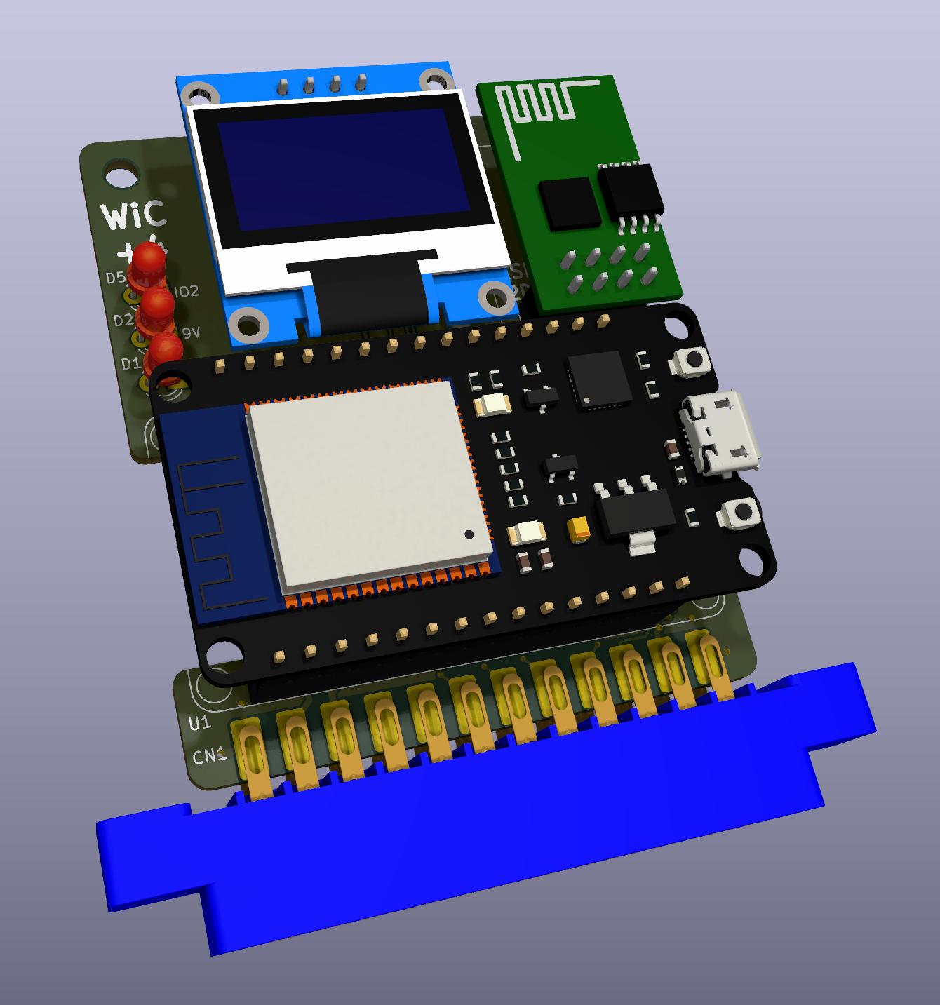
This is just a customization of the original WiC64 project in order to make it work on the Commodore +4. In fact, while this computer features a User Port that looks very similar to the one you can find on the C64, the electrical connections are different and thus some modifications are required.
The board should also be usable on a C16 or C116 through a User Port card.
Apart from the functional changes:
- I have added a jumper that selects whether the ESP should be powered by the rectified +9VAC or by the 5V rail.
- Consequently, I have added a ferrite on the 5V rail. An axial inductor should also fit, some experimentation will show what is better.
- I have switched the resistor footprints to 0805 for easier hand solderability.
The board keeps exactly the same size and major component layout, so all enclosures should still be usable.
One of my goals was to make the modifications in a way such that no changes would be required on the firmware side.
Nevertheless, this thing is completely unusable at the moment, since no computer-side software exists.
What needs to be done is to take this library and adapt it so that:
- Data I/O takes place through the User Port
- The PC2 signal (ack/strobe: byte read from/written to port, rising edge) is controlled through /DTR
- The PA2 signal (Direction: HIGH = C64/+4 => ESP, LOW = ESP => C64/+4) is controlled through /RTS
- The FLAG2 signal (ack/strobe: byte read from/written to port, falling edge) can be read through /DCD.
/DTR and /RTS can be controlled through bits 0 and 3 (respectively) of $FD02 (Note that there is an inverter gate inbetween, so they are not really active-low).
/DCD can be read through bit 4 of $FD01 (again, mind the inverter gate). An interrupt can also be set up to track its changes if required.
I recommend taking a quick look at the 6551 ACIA datasheet in order to understand how to treat the other bits properly.
Another recommendation would be to make the User Port/ACIA base addresses configurable, for those who might want to use the 16UP board in External mode.
I had actually done part of the above work, only to find out that I would then need a "launcher" program that is not open source, so I decided to stop all development.
Please refer to the original project for all documentation, firmware, drivers, etc.
If you decide to use power from the 5V rail, the diode bridge and 220uF cap can be skipped.
The ESP-01 board in the top right corner is only required for debugging.
If you want to get this board produced, you are recommended to get the latest release rather than the current git version, as the latter might be under development and is not guaranteed to be working.
Every release is accompanied by its Bill Of Materials (BOM) file and any relevant notes about it, which you are recommended to read carefully.
WiC+4 is distributed under the CC-BY 4.0 license.
WiC+4 is provided to you ‘as is’ and without any express or implied warranties whatsoever with respect to its functionality, operability or use, including, without limitation, any implied warranties of merchantability, fitness for a particular purpose or infringement. We expressly disclaim any liability whatsoever for any direct, indirect, consequential, incidental or special damages, including, without limitation, lost revenues, lost profits, losses resulting from business interruption or loss of data, regardless of the form of action or legal theory under which the liability may be asserted, even if advised of the possibility or likelihood of such damages.