Serial Bluetooth Connection for Robotique Gripper and FT Sensor
Since some robotic arms, like the UR5 do not provide a communication connection inside, it is necessary to lay the cables for connected grippers or sensors on the outside of the arm. This leads to entanglement and to unintented contact with other objects. We created a device which can be installed at the end of the arm and which provides multiple bluetooth connections, thus making the cables unnecessary.
The device is designed for the use of a UR5 with a Robotiq gripper and/or FT sensor but it can easily be altered for other arms and grippers.
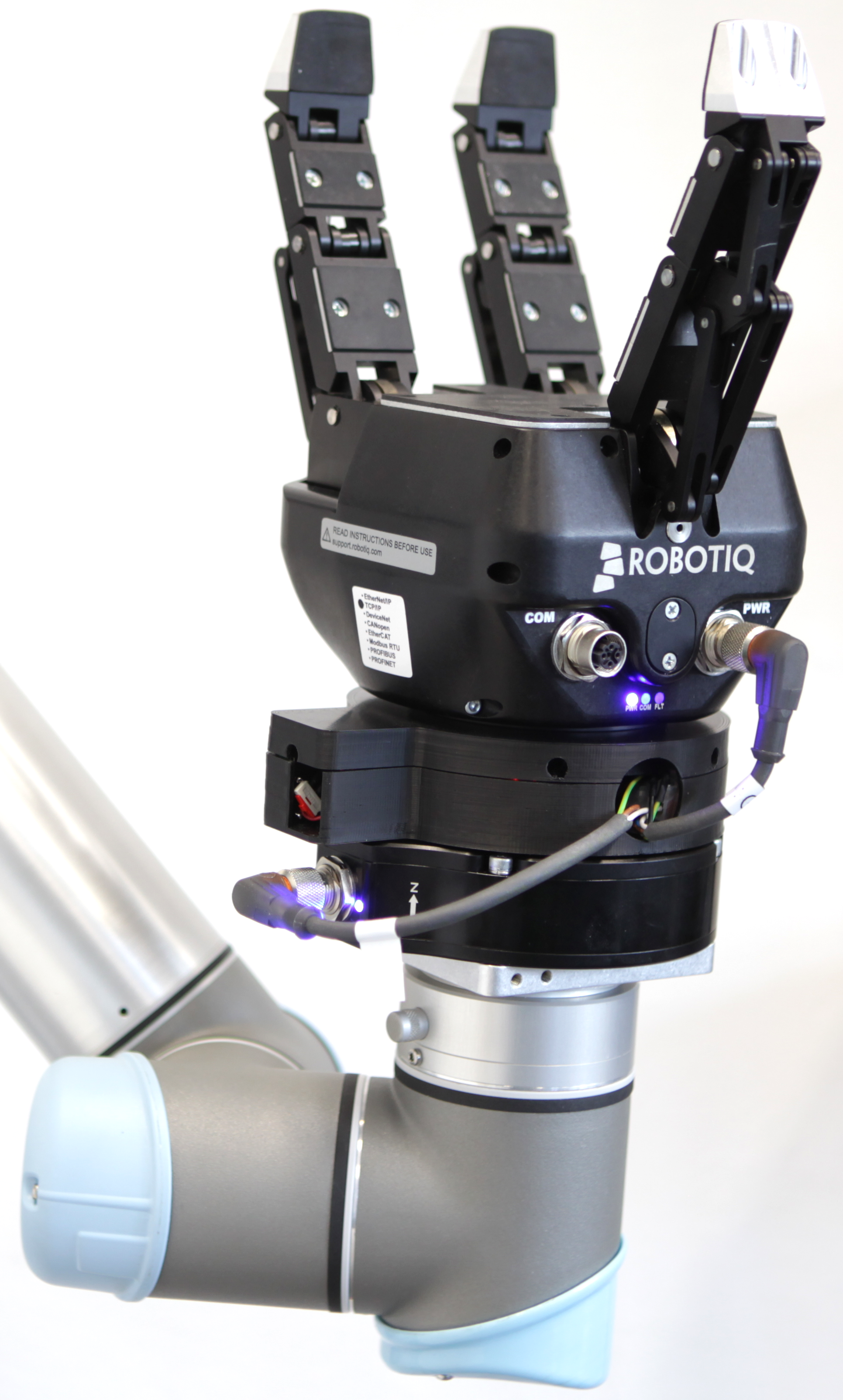
The installed device between the gripper and the FT sensor.
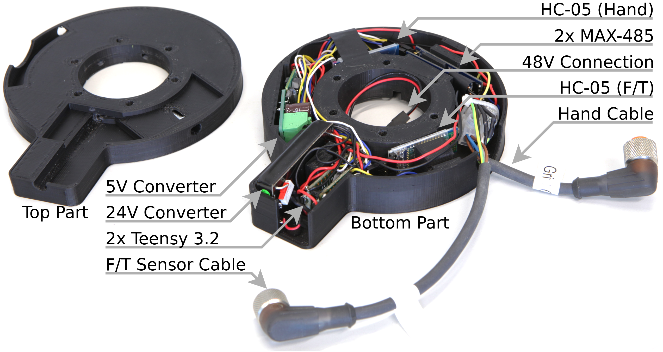
The device consits of two 3D printed parts. One is holding all electronics and one is a simple lid. The electronics are described in the following part. Up to two Bluetooth connections can be established which is necessary because the Robotiq gripper and FT sensor have the same ID but different baudrates and can therefore not be on the same bus.
Electronics
Each Bluetooth connection is provided by a chain of a HC-05, a teensy 3.2 and a RS-485 converter. The teensy is serial connected the other two chips and handles the forwarding of bytes in both directions. The necessary code can be found here. Power is provided by the UR5 as 48V. A converter is needed since the gripper and sensor need 24V. Furthermore, 5V are needed for the electronics. Therefore two converters are integrated which provide 24V and 5V. The connections are shown below.
In order to save space, the two teensy and the RS-485 converters are soldered together as a pair. The HC-05 are not soldered together to prevent interferance. Make sure that you programmed the HC-05 using the AT commands before you solder them (see next section).
Programming the HC-05
The HC-05 is programmed using AT commands. To be able to use them, we have to enter the AT mode. Do this by holding the button during power up. The LED should blink slowly afterwards. Now connect the HC-05 to a teensy and use the code to be able to send the AT commands.
Open the seriel monitor with 9600 baud using both line endings.
Test connection by sending only AT. The HC-05 should response with OK.
Now get the Bluetooth adress by using AT+ADDR?. Write it down, we will need it later.
Set the name to something usefull (linke "gripper") by using AT+NAME=.
Set the password by using AT+PSWD=.
Set the baudrate by using AT+UART=,,. Param1 is the baudrate, it should be 115200 for the gripper and 19200 for the sensor. Param2 is the stop bit, it has to be 0 for both. Param3 is the parity bit, it has to be 0 for both.
The HC-05 should now be programmed. Reconnect it to the power without holding the button to get it back into normal mode.
3D Printed Case
The case should be printed with enough infill (>=30%), since it has to be strong enough. We used ABS as material which worked very well but you can also try PLA if you want. When assembling, first put all electronics inside. The planned positions of the chips are shown below. Then put the lid on it and use the vertical screws to connect the device to the FT sensor. Afterwards, put the gripper on top of it and use the horizontal screws to fix it.
Serial Connection
With Linux it is possible to establish a serial connection via Bluetooth using rfcomm. First pair and trust the HC-05 with your computer (you can use blueman-manager if you want). Then bind the HC-05 to seriel devices using rfcomm bind /dev/rfcomm1 BTADRESS, where BTADRESS is your bluetooth adress which you noted during programming of the HC-05. You can also see it in the blueman-manager. Do the same for the second HC-05 to /dev/rfcomm2 and remember which rfcomm is connected to which device. Should you ever run into problems, use rfcomm release all to remove all seriel connections and then bind them again. You can see the current status using rfcomm -a. If you want to send manual bytes over the serial connection for testing, you can use minicom. Flash the test sketch on the teensy to test the connection. All incomming data from bluetooth will be displayed on the serial monitor.
Installation of the FT sensor, Bluetooth adapter, and the Robotiq Gripper
-
connect FT sensor to the square FT adapter, which is mounted to the UR5 end-effector link
- tighten 4 screws on the outer ring of the FT sensor with Metric screwdriver
- the top cylinder on the UR5 wrist 3 should align with the top cylinder on the FT sensor
-
connect the Bluetooth device with the FT sensor
- connect the black-red cable of the device to the exposed black-red cable from the UR5 end-effector
- put the top part of the device align with the top cylinder of the FT sensor, see figure
- tighten the 6 screws on the device with Metric screwdriver
-
connect the gripper with the Bluetooth device
- put the gripper in the correct position (the COM and PWR port side should be at the left side wrt the top side of the FT sensor)
- tighten the 6 screws, whose holes are on the curved surface of the device, by Imperial screwdriver (the yellow set, 7/64 size)
-
connect two cables coming from the Bluetooth device to the FT sensor and the gripper
- the longer cable goes to the FT sensor, the shorter one goes to the PWR port of the gripper
Troubleshooting
- Make sure that your user has the correct rights, i.e. beeing in group dialout
- In TAMS, pair the bluetooth first (password: 1234), then use
sudo rfcomm bind /dev/rfcomm1 98:D3:31:50:16:50andsudo rfcomm bind /dev/rfcomm2 98:D3:31:60:18:35 - To run these two commands while start up, copy the following codes into
/etc/rc.local.
sudo rfcomm bind /dev/rfcomm1 98:D3:31:50:16:50
sudo rfcomm bind /dev/rfcomm2 98:D3:31:60:18:35
exit 0
- If you still have error, make sure that the Bluetooth adapter of the computer is as near as possible to the robotic arm and that it is not obstructed by anything.
- If the bluetooth connection stops to work, try rfcomm release all and rebinding of the devices.
- If you update your system to
ubuntu 18.04, the default version of pymodbus install fromapt-getdoes not work, usepip install pymodbus==1.2.0to downgrade it to version 1.2.0 in your local install. - However, in Ubuntu 20.04, we need to use python3, and in python3 we cannot use pymodbus 1.2.0 as pymodbus was modified to fit python3 after version 1.3.0, so we grab the code of pymodbus 1.2.0 to our robotiq package, and make it work in python3. Now just install pymodbus via
sudo apt install python3-pymodbusis fine. - If you have any further errors (or problem solutions), please write issues or edit this file directly.


