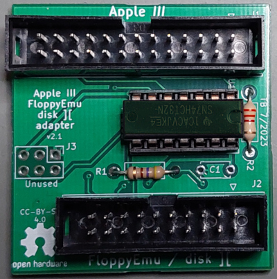
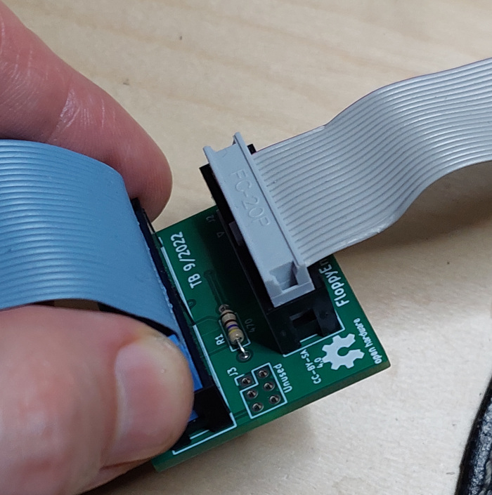
This project decribes how to build an adapter connecting an Apple III to a FloppyEmu from Big Mess of Wires - an SD-card based disk drive emulator. Alternatively, the adapter can also be used to connect the Apple III to an original Apple Disk II drive (yes, Disk II, not Disk III). The adapter works with either the internal or external floppy port of the Apple III.
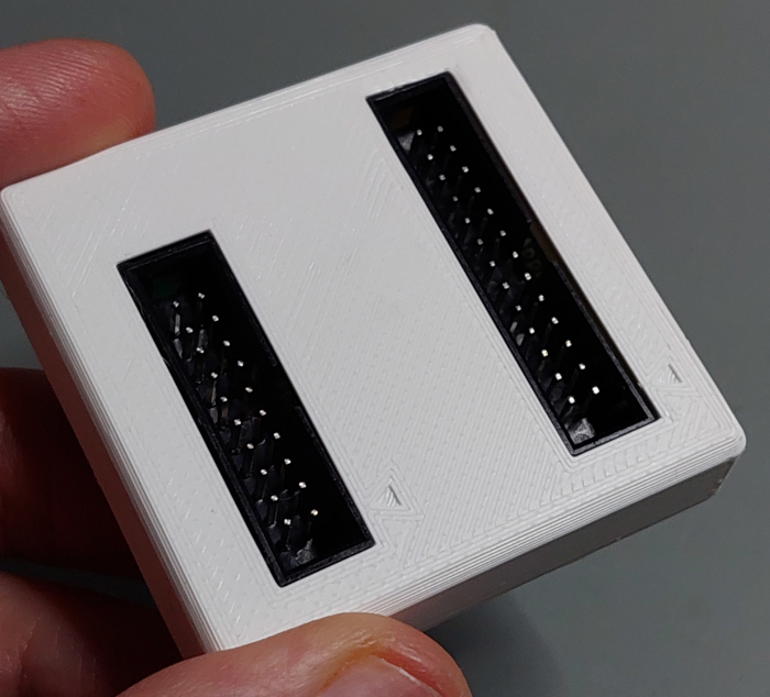
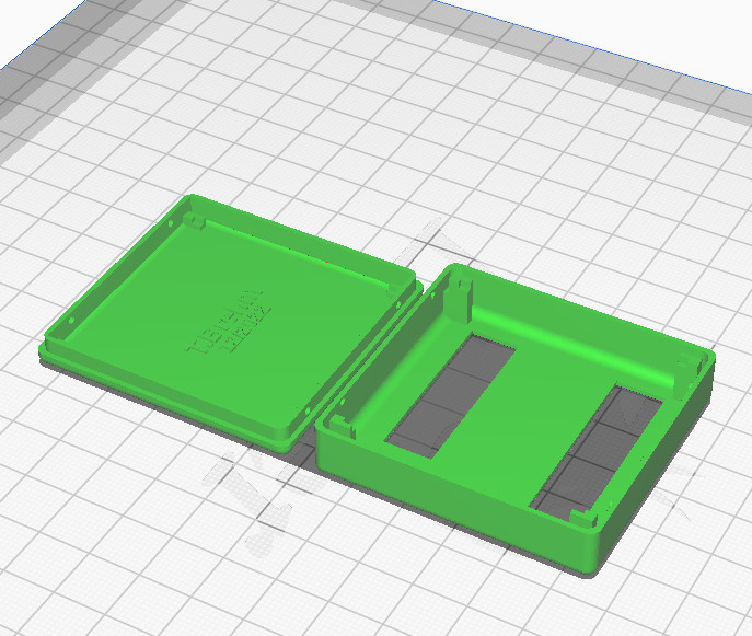
As a bonus I also added a design file for a 3D-printed slim enclosure:
This project is released under the "Creative Commons Attribution 4.0 International Public License". See LICENSE.
It doesn't take much to connect a FloppyEmu to an Apple III. The disk drive interface of the Apple III is very similar to the Apple II - with most signals being completely identical. The Apple III, however, has a few extra signals and features, hence it uses a wider 26pin connector, instead of the 20pin connector of the Apple II. Most extra pins are not required for normal operation.
A few people have made the connection between Apple III and FloppyEmu/DiskII with a simple ribbon cable: using a 26pin IDC connector at one end, and a 20pin IDC connector (stripping the top 6 wires) at the other end. That did mostly work (if you don't mess up, reverse the connectors or strip wires from the wrong side, that is...). You can find more on this in Steve's (BMOW) blog post.
However, such a simple 26pin to 20pin cable is not to be recommended - and it will not always work. For proper operation, one of the additional signals also has to be considered (see the "errata" section below, if you are interested in the details).
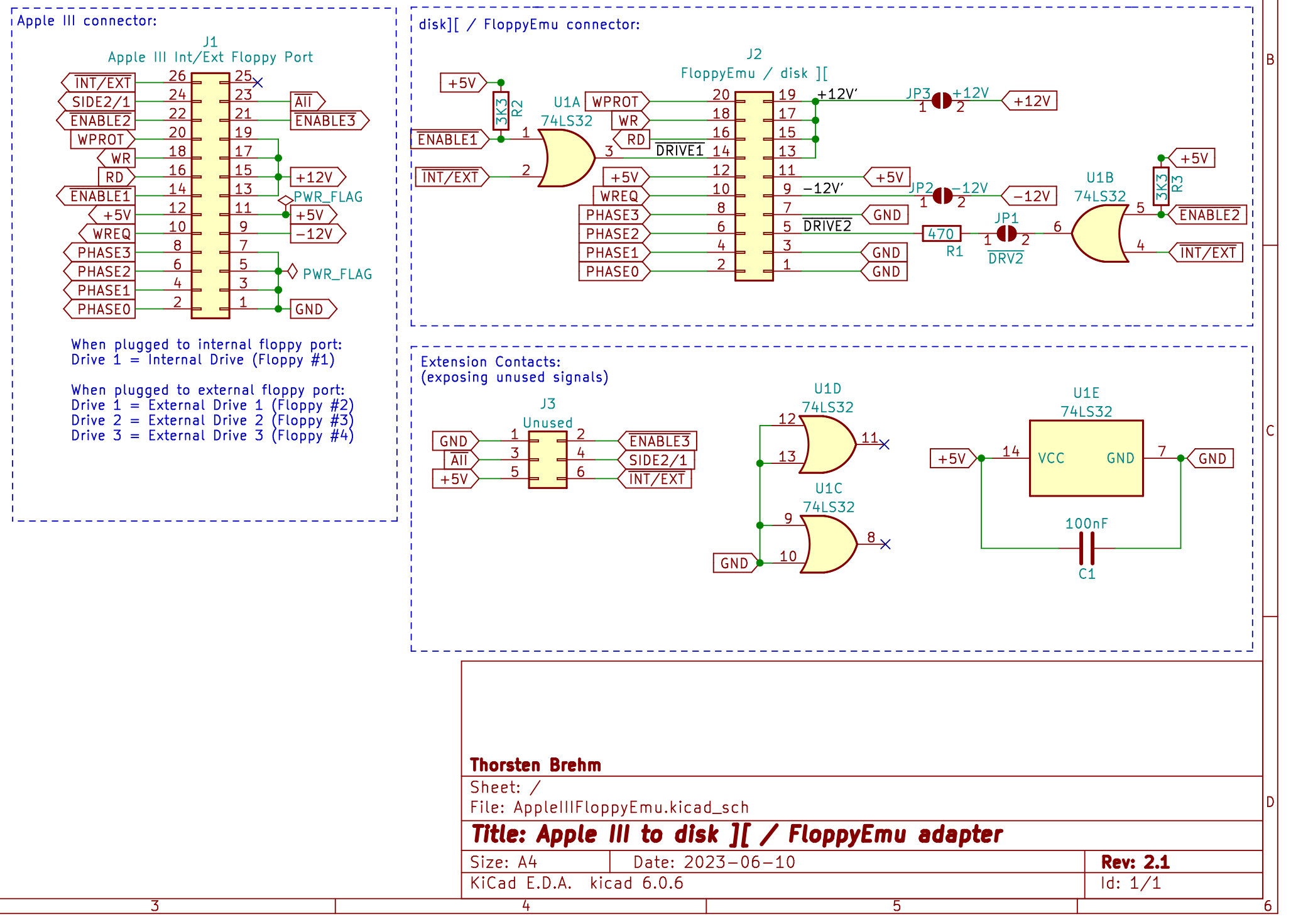
This adapter uses a cheap logic IC (74LS32) to properly decode the Apple /// drive enable signals and provide a signal to FloppyEmu or disk II. When connected to a FloppyEmu, the adapter also supports its "dual drive emulation" feature, where it emulates two separate disk drives.
The adapter can be connected to the Apple III disk port (internal or external port) and provides a standard 20pin connector, which can be used directly with the original FloppyEmu/Disk II cables.
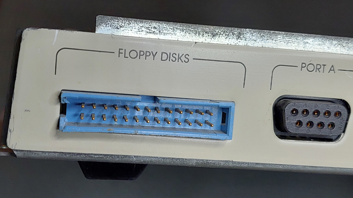
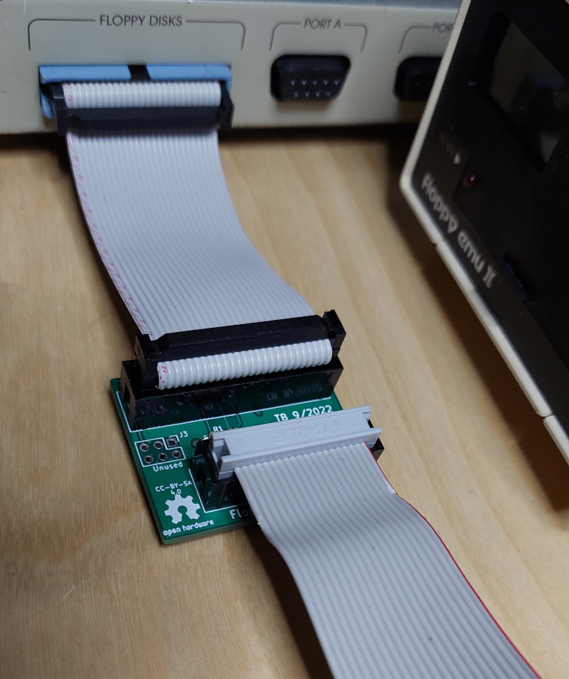
You can connect the adapter to the external floppy port at the rear of your Apple III.
- Disk II: When using the external floppy port, the connected disk II drive acts as the system's "drive #2" (".D2", which confusingly is sometimes also refered to as "external drive #1").
- FloppyEmu: When connecting a FloppyEmu, you can enable its dual drive support. In this case your FloppyEmu will emulate the system "drive #2" and "drive #3" (".D2" and ".D3" - which are sometimes also called "external drives #1 and #2"). So, including the internal drive, you then have three floppy drives connected to your Apple III.
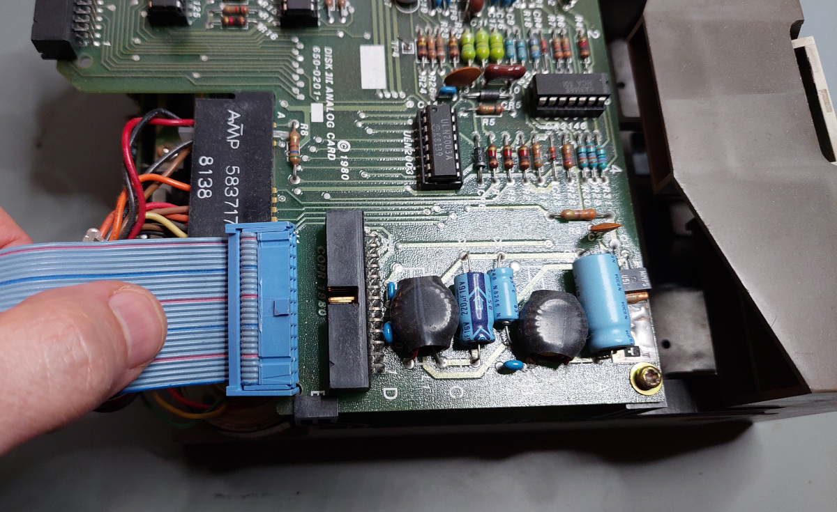
The internal port connects the boot drive (system drive #1). You can simply unplug the installed ribbon cable from the internal drive and plug it to the adapter's Apple III port. No extra cable is required.
When using the internal Apple III floppy port, the connected drive acts as drive #1 (".D1", boot drive). The internal port does not support the signals for the external drives, however. So, unfortunately you cannot make use of FloppyEmu's dual drive support to also emulate drive #2, when using the internal connector.
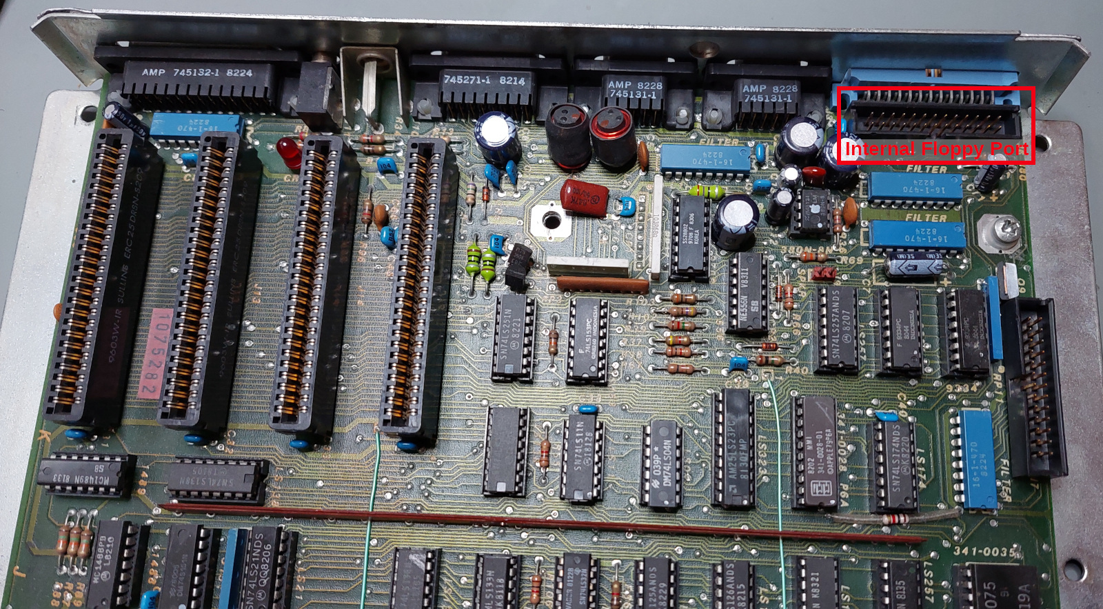
If you connect a new cable to the mainboard: the internal port is located on the mainboard right next to the external port:
Parts list for the completed PCB:
- 1x 20pin box header
- 1x 26pin box header
- 1x 14pin DIP socket (recommended)
- 1x IC SN74LS32 "OR-Gate" (74HCT32 also works but requires the optional 3K3 resistors)
- 1x 470 Ohm resistor
- 2x 3.3K Ohm resistors (optional/recommended)
- PCB (see Gerber files below)
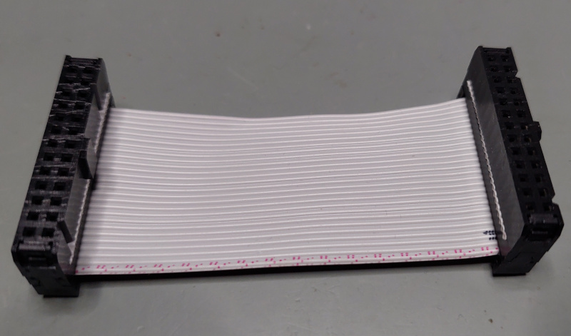
Additionally, if you wanted to use Apple III's external floppy port, you may need a short 26pin ribbon cable with appropriate IDC sockets.
- 2x 26-pin IDC socket (with strain relief)
- 1x 26pin ribbon cable (a few inches/centimers are enough)
A very short ribbon cable will be enough for the external port (since your disk II/floppyEmu already comes with a long ribbon cable). Note, if you have any wider ribbon cables, you can easily reduce them to the appropriate wire count (so you would not need to shop an entire roll of new 26-write ribbon cable).
If you make your own ribbon cable: MAKE SURE THE IDC SOCKETS ARE ORIENTED CONSISTENTLY! Do not flip or reverse the orientation of the connectors (place them on the same side of the ribbon cable and with the notch facing the same direction).
For the internal floppy port you can reuse the existing floppy cable of your Apple III (unplug the internal floppy and plug the cable into the adapter instead).
I ordered parts from my usual German electronics online shop for less than a buck. Add a few bucks if you need a new ribbon cable (Shopping List at Reichelt.de). I created a public shopping list containing all the parts. All parts are extremely common and will be available for a long time.
If you wished to directly order a PCB (PCBWay, JLCPCB etc) you could use the latest Gerber files from the Gerber directory. Just upload the ZIP file to your preferred PCB manufacturer and order the PCB. My PCBs were manufactured by JLCPCB (using the cheapest options, I got mine already after about 1.5 weeks for a few bucks/Euros).
Soldering is straight forward. Only simple through-hole components are used. All part numbers and component values are marked directly on the PCB.
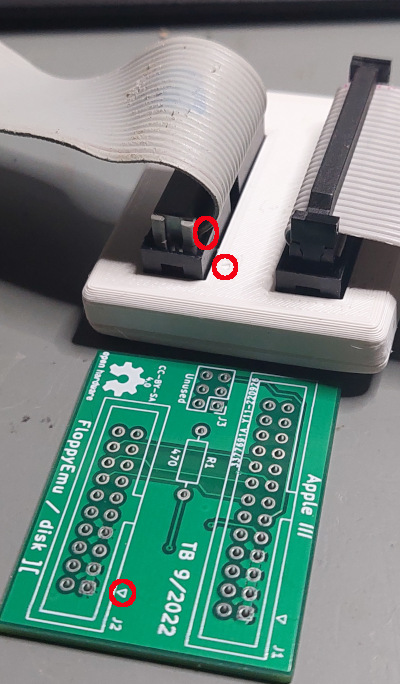
DOUBLE-CHECK THE PROPER ORIENTATION OF THE BOX HEADERS!
The notch for the box headers are clearly marked on the PCB.
Incorrect orientation of the box headers for the Apple III or FloppyEmu port will damage or destroy your Apple III and FloppyEmu/disk II drive - or both...
The capacitor (C1) was added on the PCB as a backup. It is not required (leave the slot unused).
There are three solder jumpers on the bottom side of the adapter:
- JP1: connects the "drive 2" signal to the 20-pin connector. This signal enables dual drive support of FloppyEmu. This signal cannot be used when connecting an original Apple disk II drive, though. Setting this jumper will not damage anything when a disk II drive was connected, since there is also a resistor protecting the pin. But it adds unnecessary load. So, it's recommended to only close JP1 when you connect a FloppyEmu (and intend to use the dual drive support). Otherwise leave this jumper open.
- JP2, JP3: These jumpers connect -12V and +12V to the 20pin floppy header. These voltage supplies are required for the Apple disk II drive. But they are not required by FloppyEmu. It's recommended to leave these jumpers open if you intend to only connect a FloppyEmu. But they have to be closed when you wanted to connect an original disk II drive.
Make sure the Apple III is switched off. Do not connect the adapter, the Disk II, or Floppy Emu while your machine is powered!
- Connect the adapter to the external floppy port at the rear of your Apple III (26pin ribbon cable required). Alternatively, connect it to the internal floppy port: pull the 26pin ribbon cable from the internal disk drive and plug it into the adapter.
- Finally connect the FloppyEmu's ribbon cable to the adapter. The FloppyEmu cable has a keyed connector (with a notch), so it should only fit in correct orientation.
- Alternatively, when you use the adapter to connect a Disk II drive, be extra careful: the Disk II connectors do not have a notch preventing incorrect orientation. You can easily plug them reversed, which will damage the drive and/or interface card. Pin 1 is marked with a little triangle on the PCB, on the 3D-printed enclosure - and also on the disk II connector.
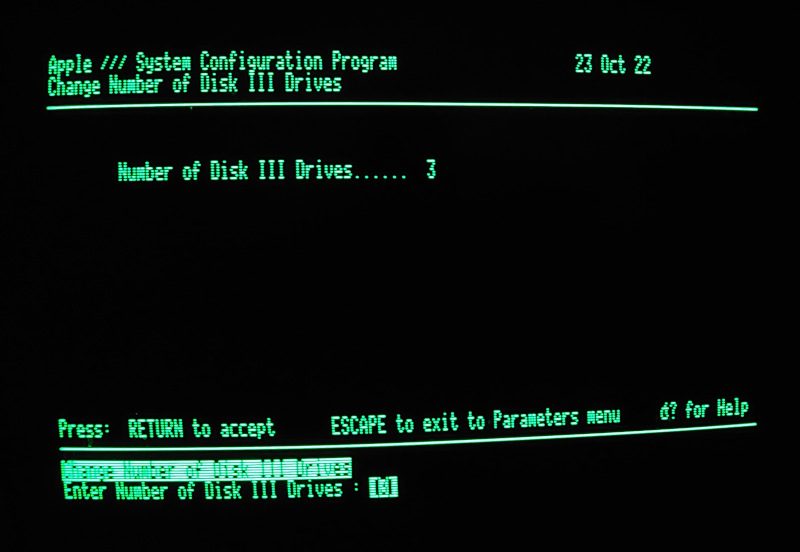
If you connect the FloppyEmu to the external connector, your system has three drives (the internal disk drive, and two external drives emulated by FloppyEmu). However, with Apple's "SOS" operating system it is necessary to configure the system to make the third drive work (if your system was previously configured for two drives only).
Here are some hints on how to configure the Apple III:
- Use the "system utilities" disk.
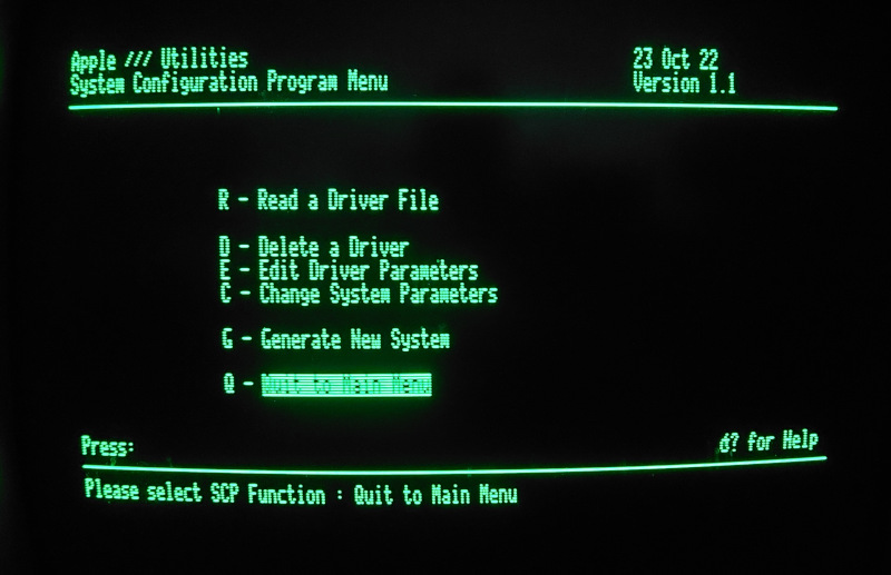
- Enter the "System Configuration Program (SCP)".
- Select "Read a Driver File" to read ".D1/sos.driver" from your boot disk.
- Select "Change System Parameters".
- Set "Number of Disk III Drives" to 3 (or 4...).
- Select "Generate New System" and write the new configuration to ".D1/sos.driver" of your boot disk.
Yes, changing the configuration of the Apple III SOS is a bit inconvenient. :) And make sure you have a backup of your boot disk, before you reconfigure anything...
As described above, a number of people have made adapters by simply stripping away the 6 additional signals from the wider Apple III connector, and connect the 20 identical signals to a FloppyEmu/Disk II (in fact: the first version of the adapter in this project also followed this basic approach).
This will mostly work - when each drive is used individually. However, the Apple /// has a feature, which Apple IIs do not have: the Apple /// disk drive logic is able to keep the motor of the internal disk drive and one external disk drive spinning concurrently. This significantly speeds up the performance when copying data between internal and external disks - or when quickly reading files from both drives. The computer is no longer delayed by waiting for drive to reach their target rotation speed, when the drives keep spinning concurrently.
This feature is used on the Apple ///, for example, when using the "volume copy" feature of "SOS system utilties". While copying an entire disk, it keeps both drives spinning, while reading data from one disk and immediately writing it to the other. Disk copying is therefore much faster on the Apple III than on an Apple II (where the computer again and again needs to briefly wait while the two drives spin up and down).
This feature is implemented by Apple /// by keeping the enable signals for the internal and one of the external drives both enabled. These signals are at the same pin location as the respective signals of Apple II drives. However, on the Apple II it is forbidden for more than one drive to be enabled concurrently, since this would result in a conflict on the other shared communication signals. On the Apple II these signals meant "enable motor and communication". The Apple ///, however, has an additional signal on its 26pin port, which selects between internal and external communication. The disk enable signal on the Apple III only means "enable motor" - and therefore allows more than one drive to be enabled (spinning) at the same time. Still, communication always takes place with one drive only, when additionally an extra signal on the 26pin connector selects the internal port (or external port, respectively).
This adapter uses a simple 74LS32 logic IC (OR-gate), which properly considers all Apple III disk enable signals - and provides the correct signal to FloppyEmu (or disk II).
If you use CMOS logic devices (74HCT32) then the two pull-up resistors are required (they are recommended anyway).
The KiCad folder contains the schematics and PCB project files, if you wished to adapt the design.
As a bonus, I also added a design for a 3D-printed enclosure. It's a neat and slim box which completely covers the PCB - eliminating any risk of creating short-circuits (remember the bottom side of the PCB has +/-12V and +5V voltage pins - so it's a good idea to cover them). You'll find the 3D file (.stl) in the /3DPrint folder.
