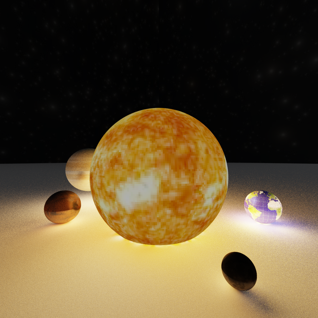
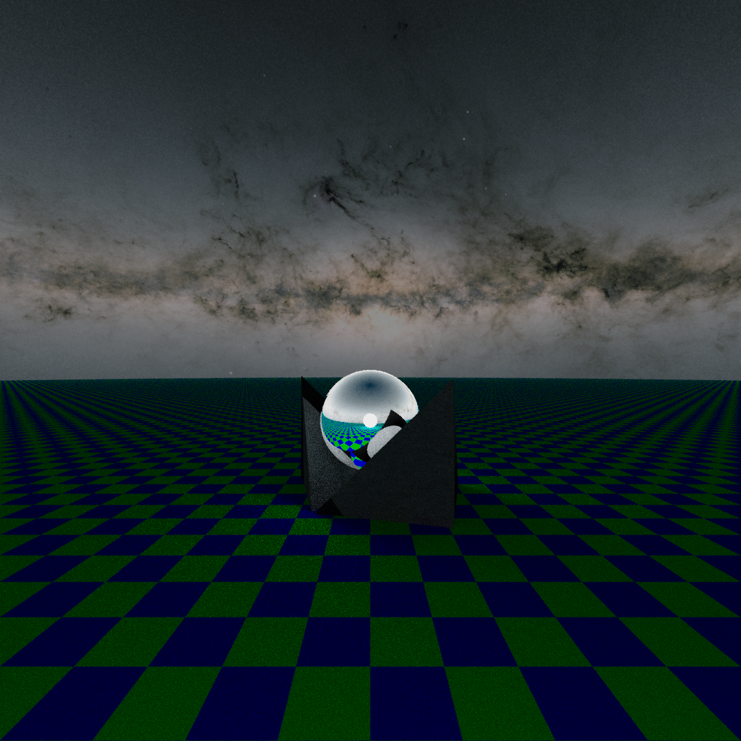
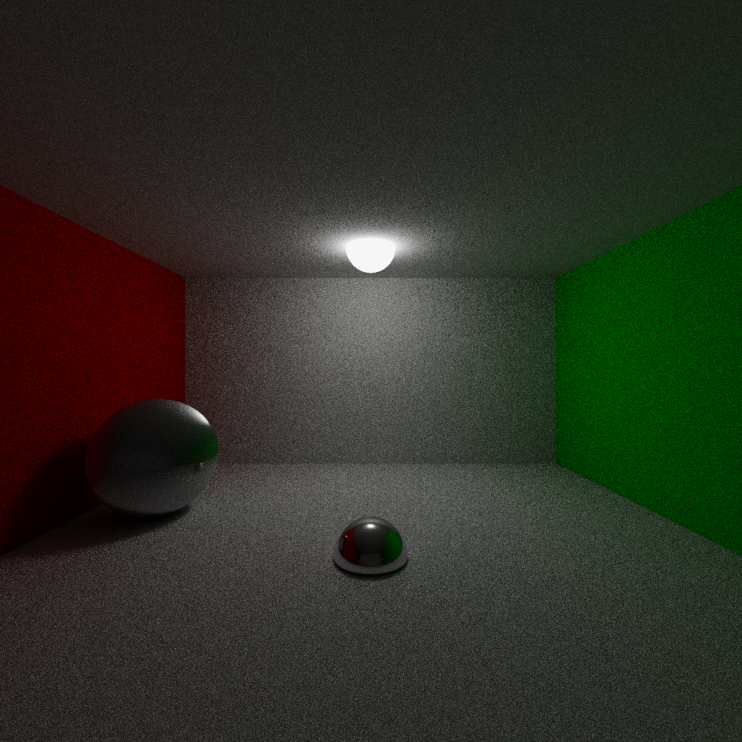
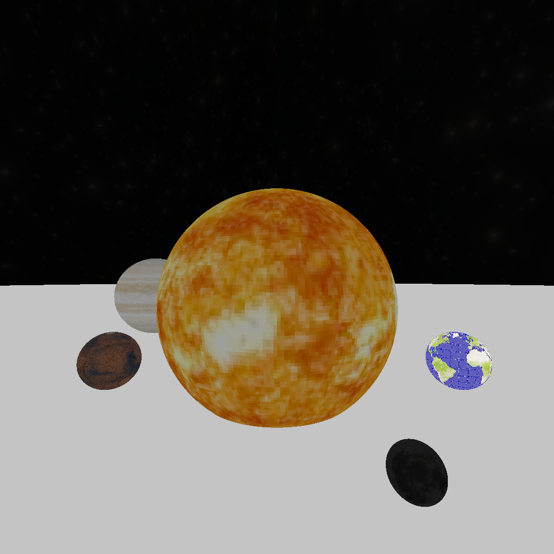
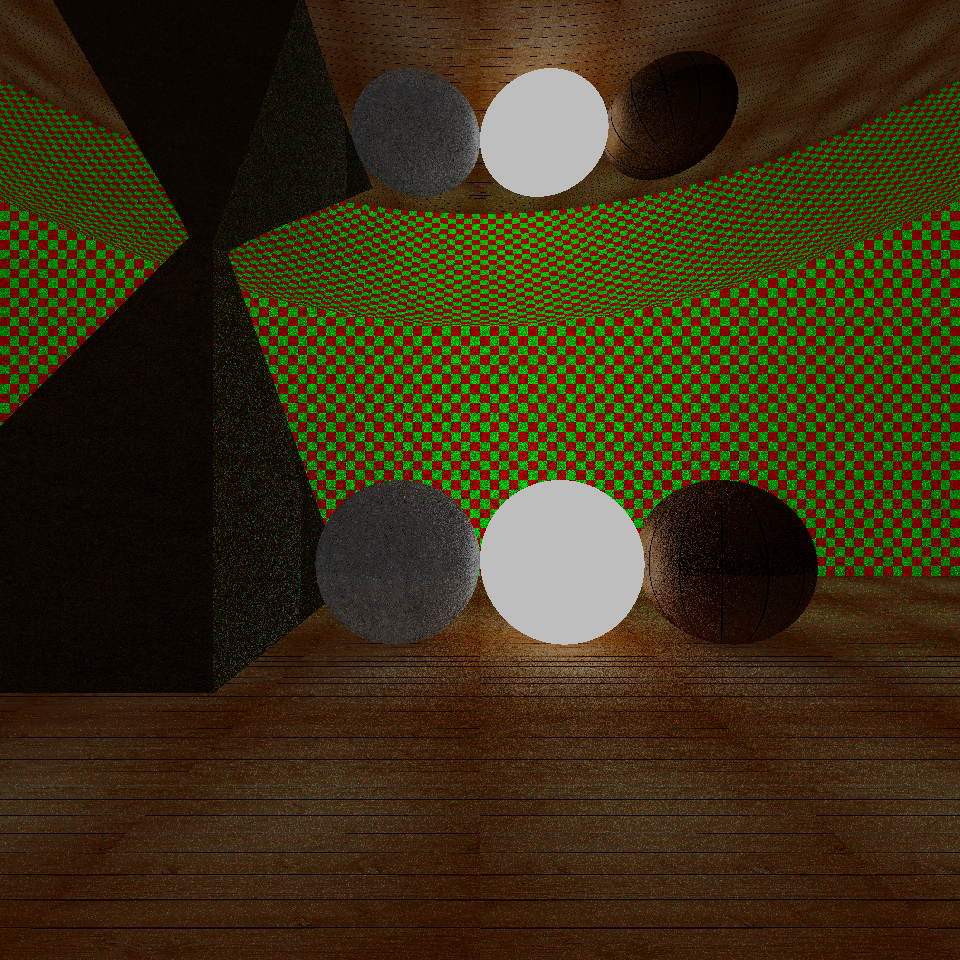
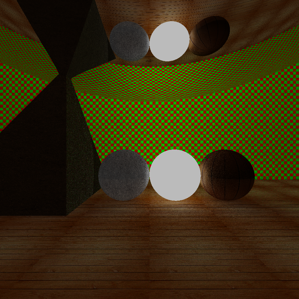
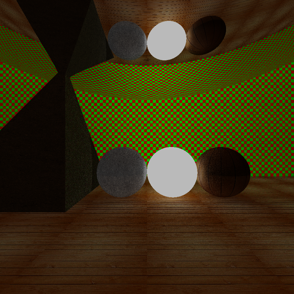
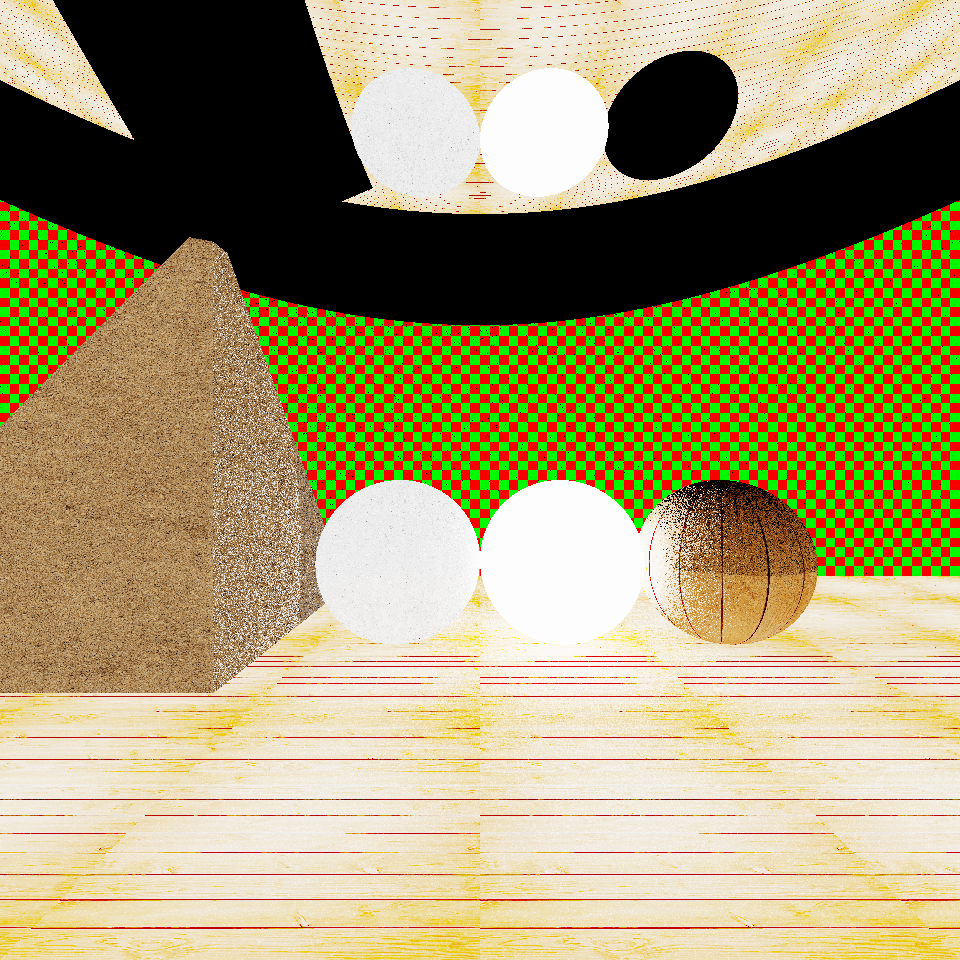
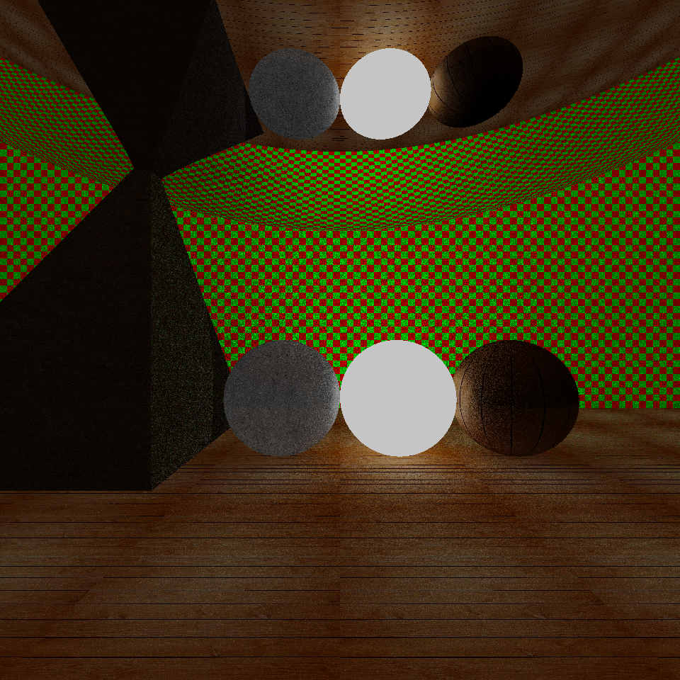
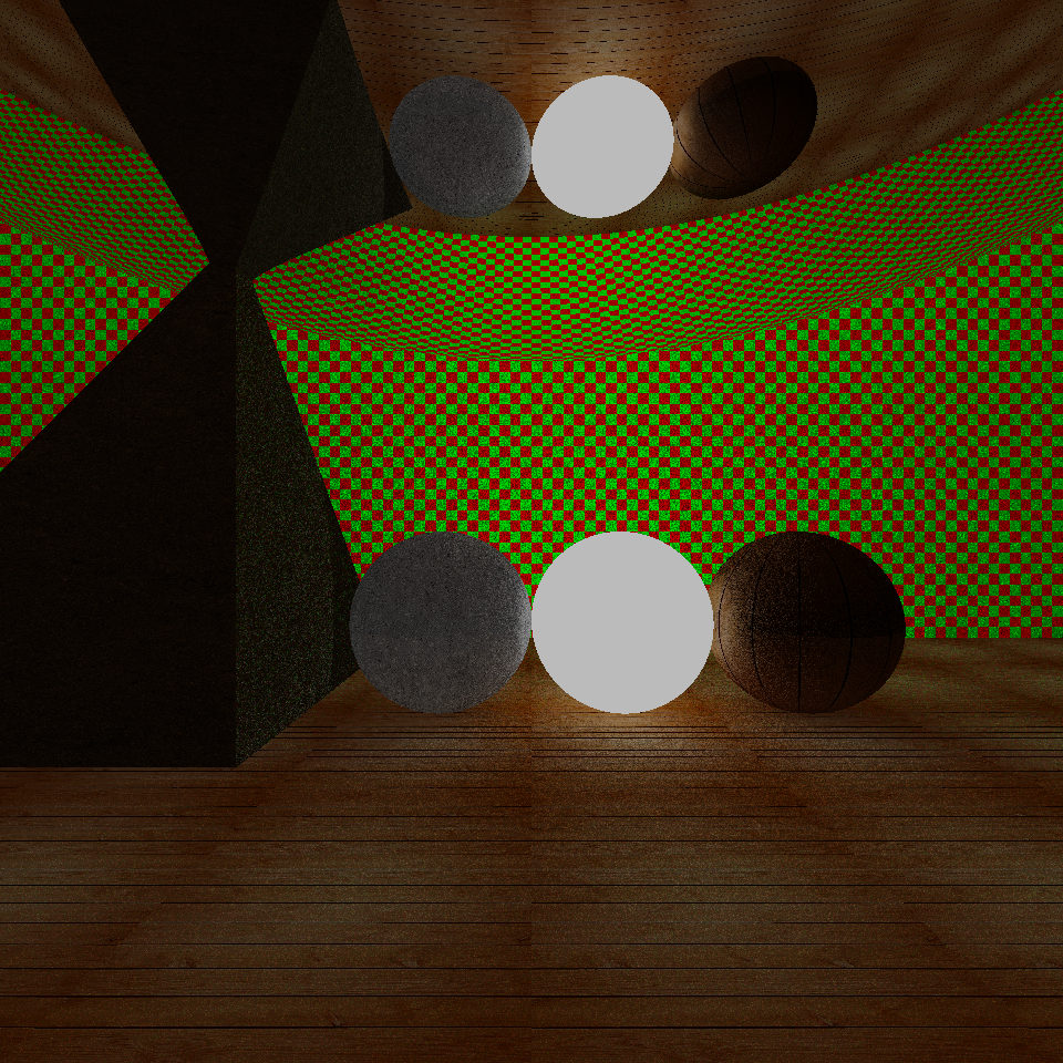
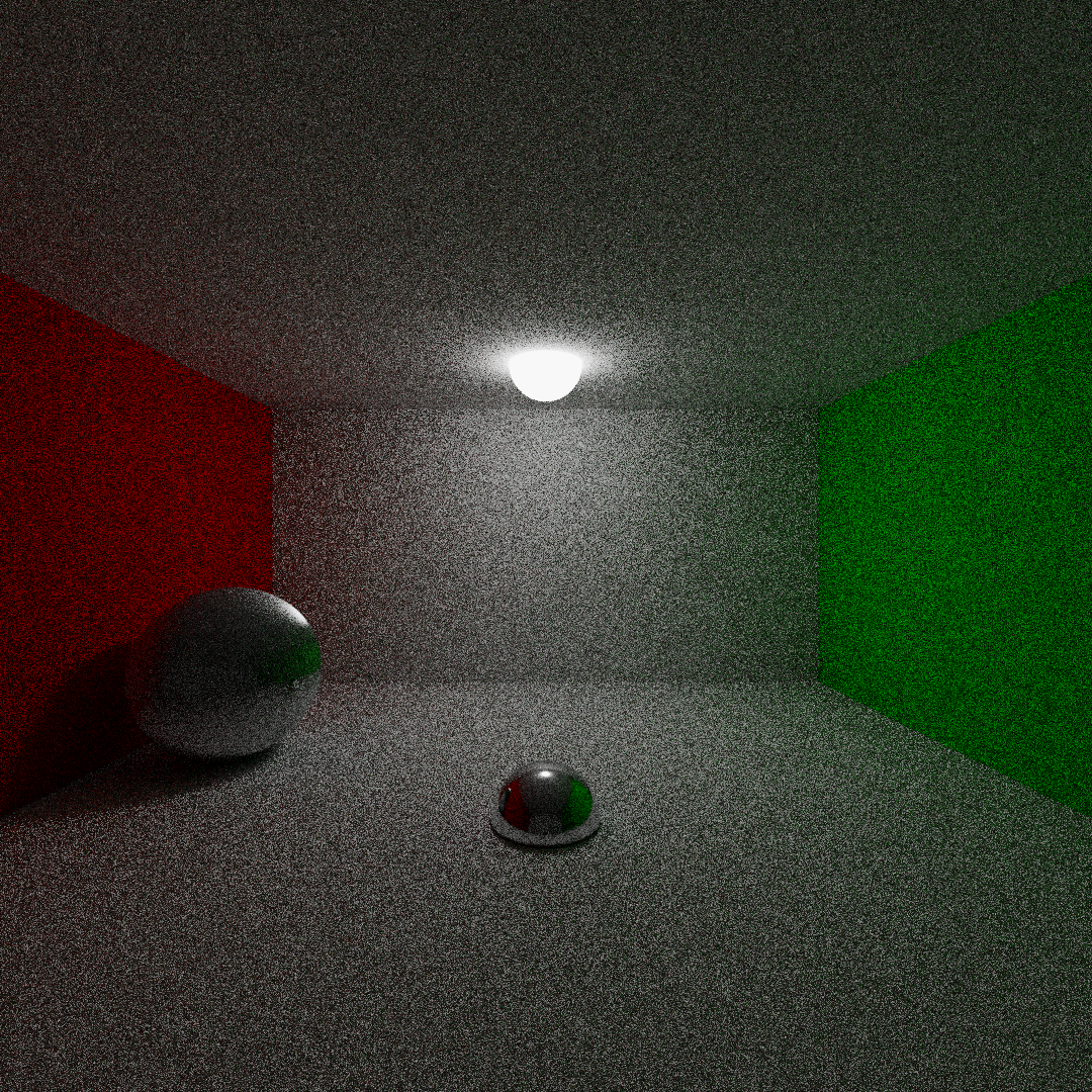
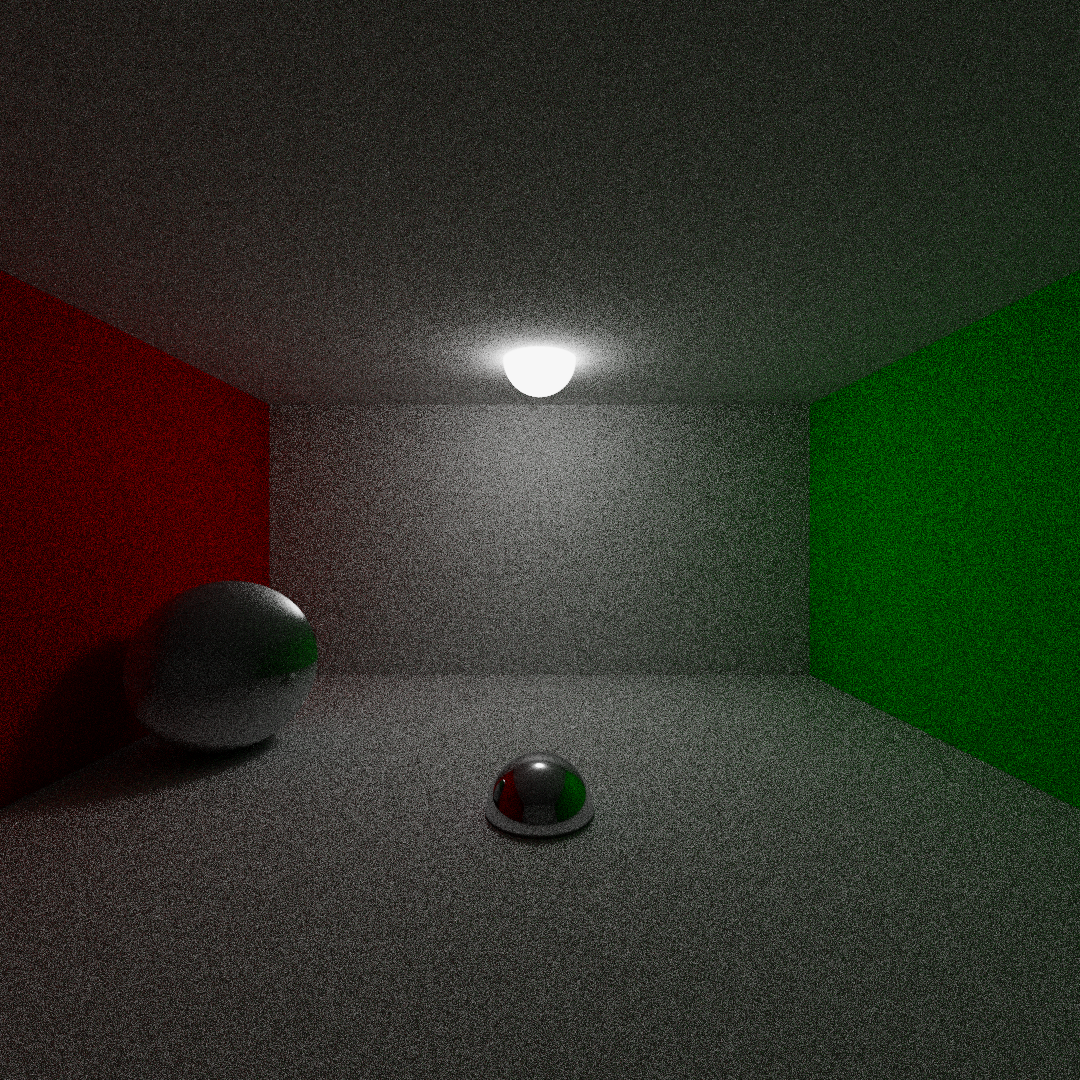
LITracer is a photorealistic images generation software developed using Ray-Tracing technique to simulate the realistic behavior of light reflection.
LITracer allows the user to define a scene using different geometrical objects and use different rendering algorithms to generate a photorealistic image of the scene.
This raytracer was developed during Professor Maurizio Tomasi's course Numerical techniques for the generation of photorealistic images
The code is written in Kotlin language using Gradle software.
To obtain this code, in order to run or modify the program, download the zip file from the latest version or clone this repository using the command git clone https://github.com/TommiDL/LITracer
The presence of jdk version 21 is requested as a fundamental prerequisite for the correct functioning of the program
To satisfy the requested dependencies in order to run this code use the command ./gradlew build.
Finally run the command ./gradlew test to check the correct behavior of the code.
LITracer can perform five tasks:
-
Render: render an image from a scene defined in a text file
-
Demo: Create a demo image, useful to gain confidence with the software usage.
-
pfm2png: convert a PFM file into a PNG image using the requested conversion parameters
-
png2pfm: convert a PNG image into a PFM file usable to define the pigment of objects in scene's declarations
-
Merge-Images: Merge multiple images into one,
Useful to lower the noise using different importance sampling random seeds (see Render)
Reads a scene declaration from a text file and create a pfm file and a png image of the scene using different rendering algorithm.
The user is allowed to choose between perspective or orthognal point of view.
The available rendering algorithms are the following:
-
onoff: the objects of the scene are displayed in white color with a black background.
Here some examples using onoff rendering algorithm.
-
flat: the objects of the scene are displayed with their real colors without simulating the realistic behaviour of light
Here some examples using flat rendering algorithm.
-
path tracing: the objects are displayed with their real colors and physical properties simulating the realistic behaviour of light
Here some examples using pathtracing rendering algorithm.
See the tutorial to make a scene declaration file or try using the example.txt file with the command:
./gradlew run --args="render example.txt -pfm example -png examples
Basic Usage of render command:
`./gradlew run --args="render <scene_file.txt> --algorithm=<render_alg> -pfm <output_pfm_file_path> -png <output_png_file_path>"`
All the images will be saved in the images folder.
Useful flags:
-pfm,--pfm-output: set the name in wihch the software save the pfm output file [default value output.pfm]-png,--png-output: set the name in which the software save the png output file [default value null]-alg,--algorithm: Select rendering algorithm type [default value pathtracing]:- onoff -> rendering in black&white format
- flat -> rendering in colored format
- pathtracing -> rendering with pathtracing alg
--bck-col:set Background Color [default value black]-w,--width: set the width of the PNG image [default value 480]-he,--height: set the height of the PNG image [default value 480]
Pathtracing useful flags:
-
--nray: set the number of scattered rays to generate after a surface collision in pathtracing algorithm [default value 10](exponential growth of time complexity)
-
-samples,--samples-per-pixel: set the number of ray per pixels to process the color using importance sampling [default 1](linear growth of time complexity)
-
-seed,--samples-seed: set the seed for the importance sampling rays production -
-md,--max-depth: set max depth of bouncing per ray [default value 3] -
-rr,--russian-roul: set the value of depth to start suppressing the ray bouncing probability [default value 3]
For further details execute ./gradlew run --args="render" and get the complete usage documentation.
Create a pfm file of a demo scene and (optionally) a PNG image. This functionality is meant to take confidence with the usage of the code.
The demo command also allows the user to move inside the scene specifying the translation and rotation movements.
Basic usage of demo command
`./gradlew run --args="demo --camera=<camera_type> --algorithm=<render_alg> -pfm <output_pfm_file_path> -png <output_png_file_path>"`
For further details execute ./gradlew run --args="demo" and get the complete usage documentation.
Execute conversion from a PFM file to a PNG image with the specified values of screen's gamma and clamp factor
Usage of pfm2png
`./gradlew run --args="pfm2png <input_PFM_file>.pfm <clamp value (float)> <gamma value of the screen (float)> <output_png_file>.png"`
For further details execute ./gradlew run --args="pfm2png" and get the complete usage documentation.
Execute conversion from a PNG image to a PFM file with the specified values of screen's gamma and clamp factor
`./gradlew run --args="png2pfm <output_PFM_file>.pfm <clamp value (float)> <gamma value of the screen (float)> <input_png_file>.png"`
For further details execute ./gradlew run --args="png2pfm" and get the complete usage documentation.
The command take in input several PFM files of the same scene and merge them in a singular PFM file and PNG image to create a less noisy image of the scene.
The single PFM file has to be created using the render command, passing it unique values for the importance sampling seed with the flag --samples-seed .
See here an example.
`./gradlew run --args="image-merge [<input_pfm_files>] -pfm <output_pfm_path> -png <output_png_path>"`
For further details execute ./gradlew run --args="image-merge" and get the complete usage documentation.
Here a comparison of the same image using the three different algorithms:
From the left to the right: (1) pathtracing algorithm, (2) flat algorithm, (3) onoff algorithm
Here is an example made with 11 spheres showing the behavior of on-off renderer using the two different choices of camera
The image on the left was generated using perspective camera, the image on the right was generated using orthogonal camera
Here some examples obtained using ./gradlew run --args="demo -alg flat"
Demo image obtained using flat tracing algorithm, on the left image generated using perspective camera, on the right image generated using orthogonal camera with a rotation of 45 degree relative to the z-axis
Here some examples obtained using ./gradlew run --args="demo -alg pathtracing".
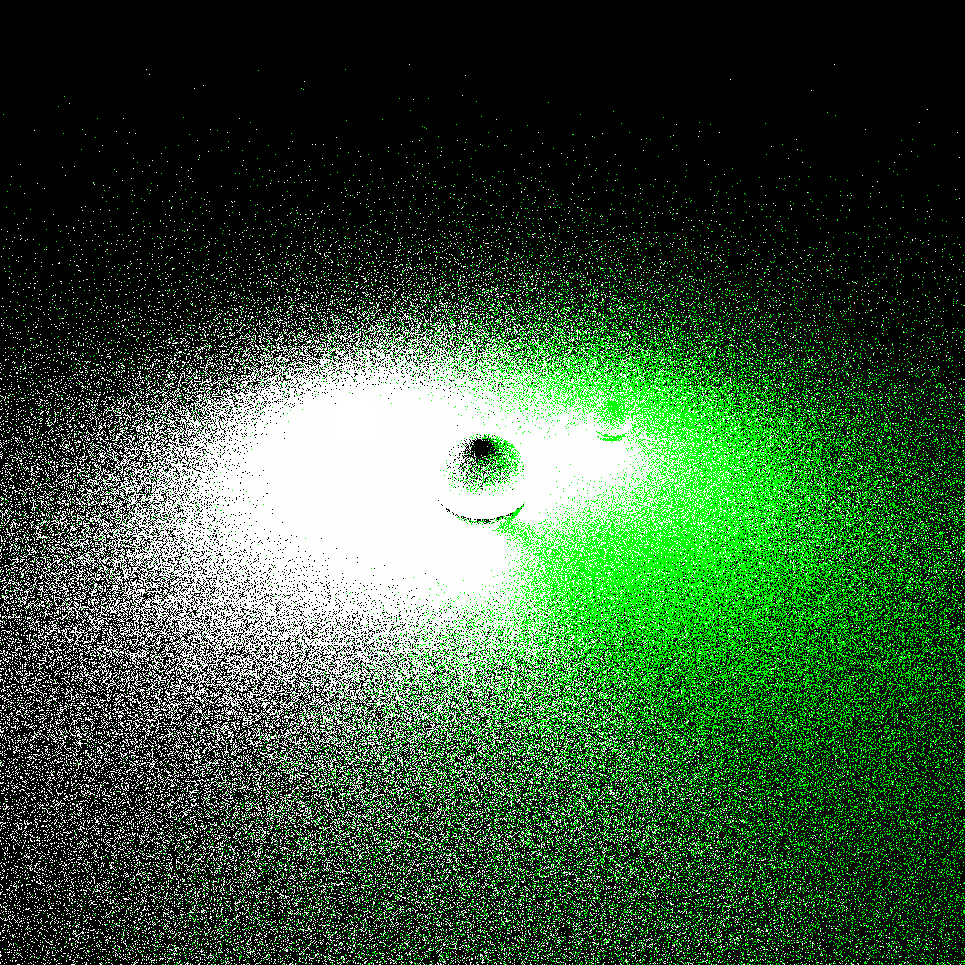
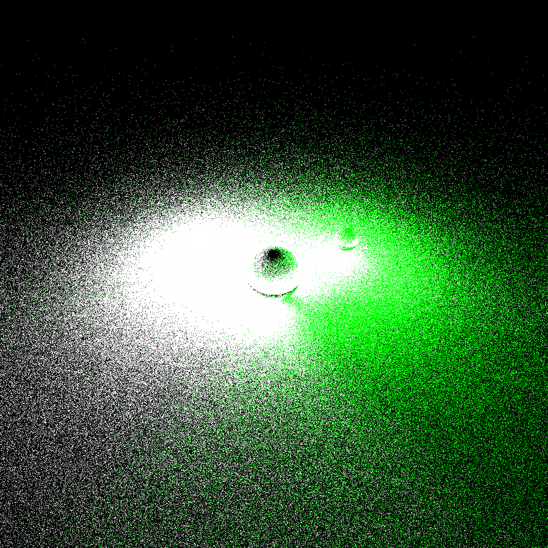
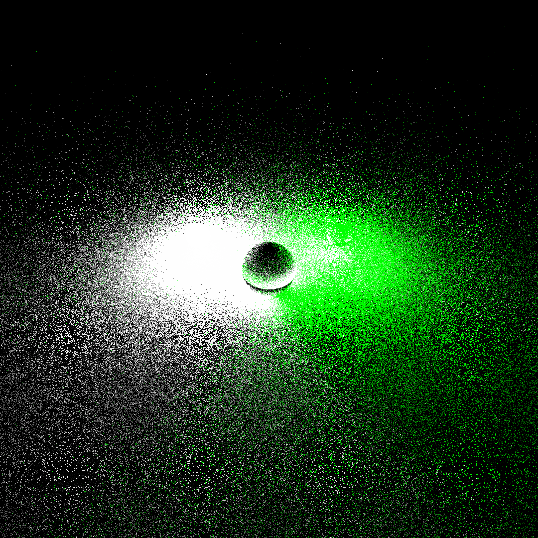
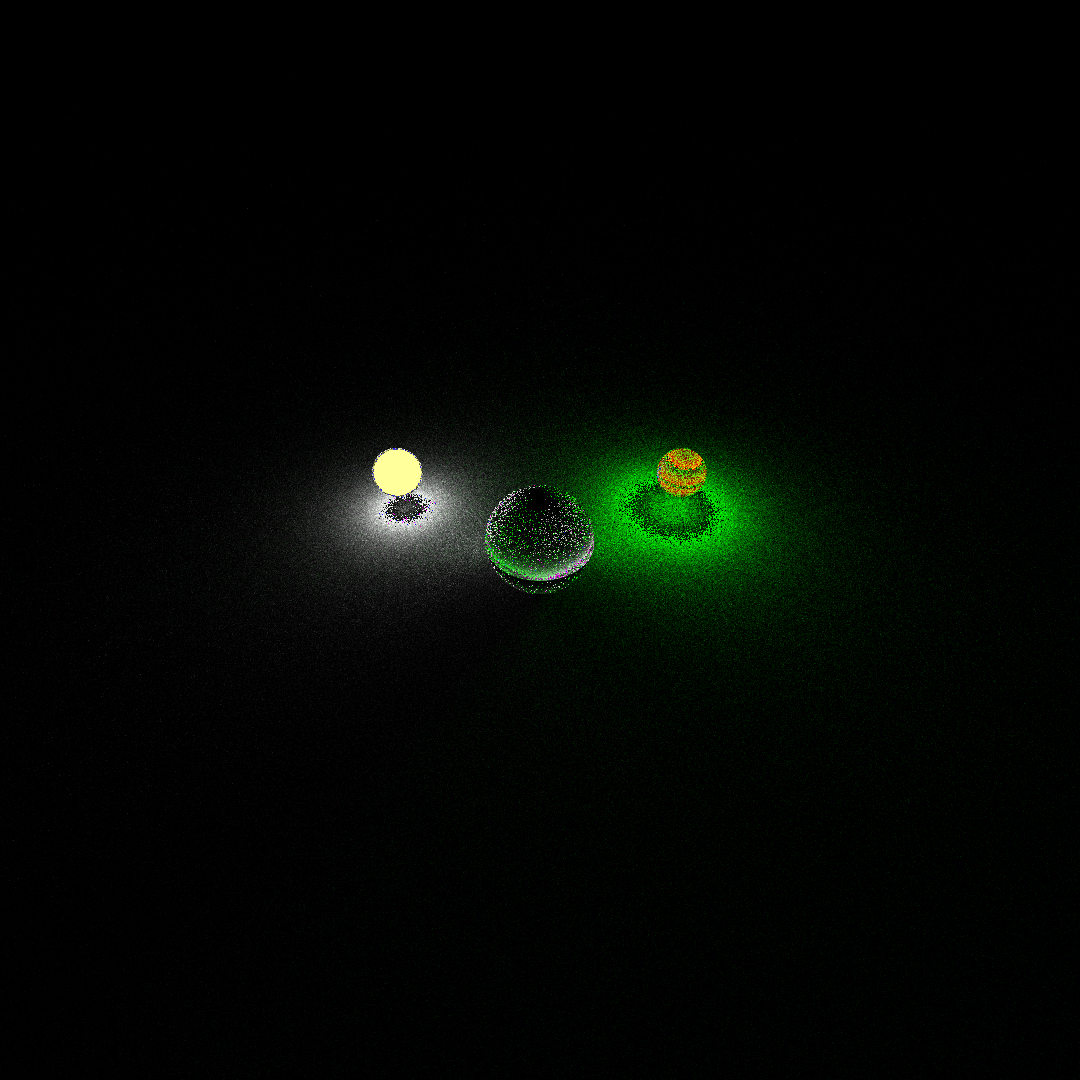
The following examples of the demo image were generated using the path-tracing algorithm for different values of the parameter --nray with perspective camera.
Each one of those images is obtained with a value of max depth fixed at 3.
On the left demo image obtained with nray=1, on the right demo image obtained with nray=5.
On the left demo image obtained with nray=15, on the right demo image obtained with nray=20.
The following example is generated using orthogonal camera with parameters --nray=10, a traslation of 0.5 along z axis and of 10 along x axis and a rotation of 45 degrees relative to the z axis
Demo image with orthogonal camera (800x500 pixels)
Finally some examples generated using a fixed value of --nray=10 with different values of the max depth using perspective camera
From the left to the right: (1) max depth = 1, (2) max depth = 2, (3) max depth = 3
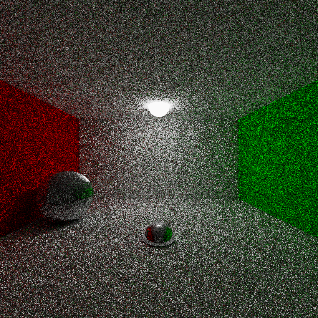
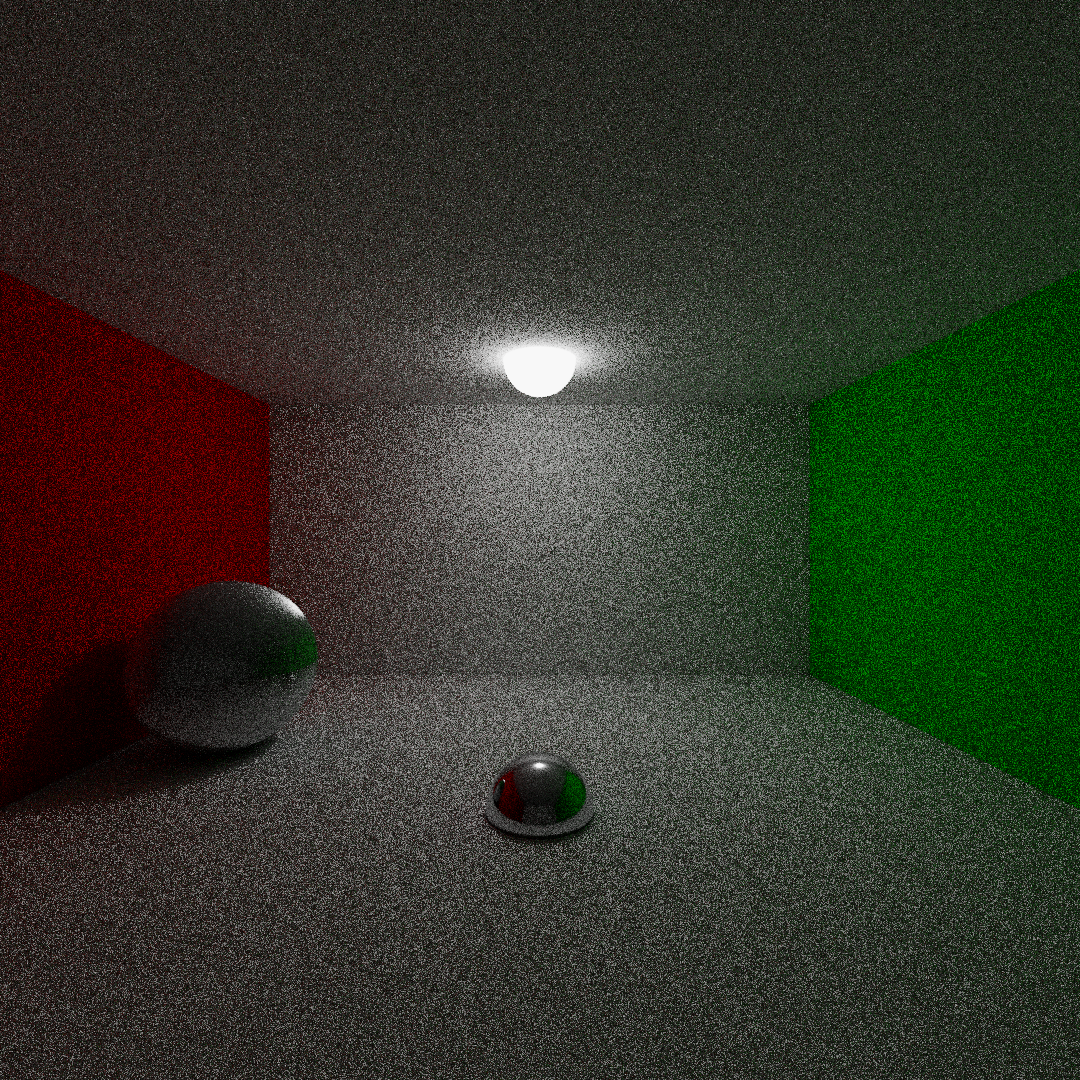
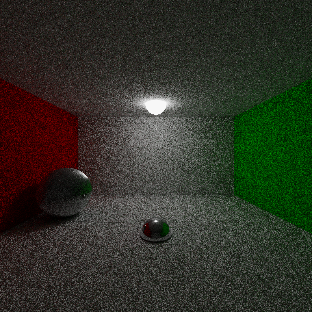
Here some examples of a cornell box like image using different values of --nray and --samples-per-pixels
5 scattering rays per hit
From the left to the right: (1) samples = 1, (2) samples = 9, (3) samples = 16
From the left to the right: (1) samples = 25, (2) samples = 36
7 scattering rays per hit
From the left to the right: (1) samples = 4, (2) samples = 9, (3) samples = 16
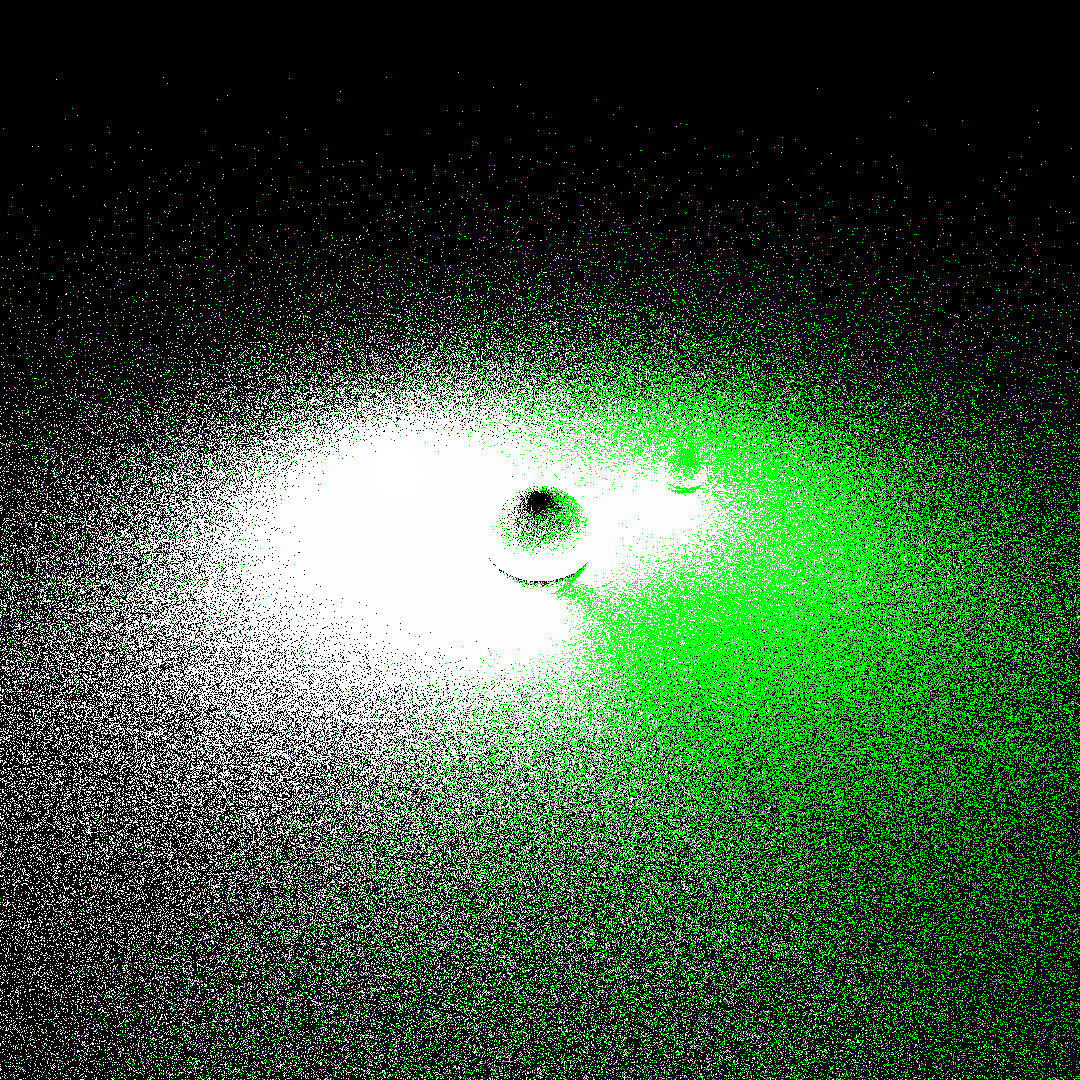
Here an example of several images generated using different samples-seed values merged using the command image-merge
several images generated with different random seeds
Merged image
See the file CHANGELOG.md to have a full insight on LITracer's version history
The code is released under the Apache License version 2.0. See the file LICENSE.md


