The ATtiny1627 family of microcontrollers contains an Analog-to-Digital Converter (ADC) with an embedded Programmable Gain Amplifier (PGA). This demo shows the PGA and ADC by acquiring a PGA amplified sample once per second. Other peripherals used in this demo include the Real-Time Counter (RTC), Event System (EVSYS) and the Configurable Custom Logic (CCL).
- MPLAB® X IDE v5.50 or newer
- MPLAB XC8 v2.30 or newer
- MPLAB Code Configurator (MCC) v5.0.3 or newer
- ATtiny_DFP v2.7.128 or newer
- MPLAB Data Visualizer Plugin or serial terminal
- ATtiny1627 Curiosity Nano Evaluation Kit (DM080104)
- Running at 3.3V (default)
- Variable Power Supply or Other Signal Source
- Breadboard and Wire (for connecting)
To enable floating point Printf support on AVR devices, add the following settings to the XC8 linker options:
-Wl,-u,vfprintf -lprintf_flt -lm
| I/O Pin | Name |
|---|---|
| RB2 | UART TX |
| RB3 | UART RX (unused) |
| RB5 | Analog Input (+) |
| RB7 | LED0 |
| RC4 | Switch 0 (SW0) |
UART - 9600 Baud, 8-bits, No Parity, 1 Stop Bit, Printf support
ADC (Non-PGA Settings) - Single Sample, Triggered on Event (Channel 0), AQ time = 100 cycles, VREF = VDD, Run Standby (set in main)
ADC (PGA Settings) - PGA Enabled and Connected, PGA Sample Time = 6 Cycles, 1/4 Bias Current
RTC - 1kHz Internal Oscillator, PIT Enabled, PIT Period = OFF
EVSYS - Channel 0 Event Generator: RTC / 1024
CCL - Connected to SW0, Run Standby, D-input Flip-Flop Synchronized to 1 kHz internal oscillator, Filter Enabled
The first step is to open the MPLAB Data Visualizer tool by pressing the "DV" icon in the toolbar as shown below.
If this icon is not shown, please install MPLAB Data Visualizer in the Tools → Plugins window before continuing.
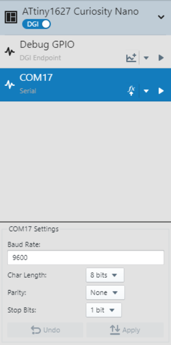
Then select the COM port associated with the Curiosity Nano by clicking on COM port entry. Set any settings required in the box below (defaults are OK for this example).
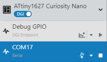
When the correct COM port has been selected and the Data Visualizer settings are set, press the play button to open the COM port.
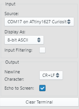
Once the COM port has been opened, the last step is to set the terminal window to use the COM port as a data source.
This demo periodically amplifies then acquires a single-ended analog input signal to the ADC, then prints the measured result about once per second.
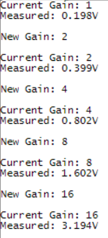
LED0 on the microcontroller toggles when ready to print a result. The current gain of the PGA and the result are printed to the UART terminal at 9600 baud (see example image below). Once the UART is idle, then the microcontroller enters Standby Sleep to save power.
To switch the set gain, the input signal from SW0 is debounced by a CCL. The rising edge interrupt from the CCL wakes the microcontroller to:
- Stop the RTC
- Modify the gain of the PGA (1x, 2x, 4x, 8x, 16x, then repeat)
- Print the new gain to the terminal
- Restart the RTC
- Return to Standby Sleep
This demo has demonstrated the PGA functionality of the ADC to acquire small signals in the ATtiny1627 family of microcontrollers.


