Implements the client side of RF24SN. For full description of protocol, client server setup or alternative implementations, see RF24SN
cd /path/to/arduino
cd libraries
git clone https://github.com/VaclavSynacek/RF24SN_Arduino_Client.gitall of these includes are required:
#include <SPI.h>
#include "RF24.h"
#include "RF24SN.h"
update depending on your wiring setup. With the default wiring described underneath this should be ok:
#define RF24SN_NODE_ID 1
#define RF24SN_SERVER_ADDR 0xF0F0F0F000LL
#define RF24_CE_PIN 9
#define RF24_CS_PIN 10

RF24 radio(RF24_CE_PIN, RF24_CS_PIN);
RF24SN rf24sn( &radio, RF24SN_SERVER_ADDR, RF24SN_NODE_ID);

void setup(void) {
	rf24sn.begin();
}
To send single float value to MQTT broker use publish function:
#define SENSOR_ID 1  //publishes to RF24SN/in/<RF24SN_NODE_ID>/1

float measuredValue = 3.14; //replace this line with actual sensor reading code
bool publishSuccess = rf24sn.publish(SENSOR_ID, measuredValue);
To request single float value from MQTT broker use request function:
#define SENSOR_ID 2  //request last payload fo RF24SN/out/<RF24SN_NODE_ID>/2

float requestValue;
bool requestSuccess = rf24sn.request(SENSOR_ID, &requestValue);
if(requestSuccess)
{
   Serial.println(requestValue); //replace this line with some action code (moving servo, LED on, etc.)
}
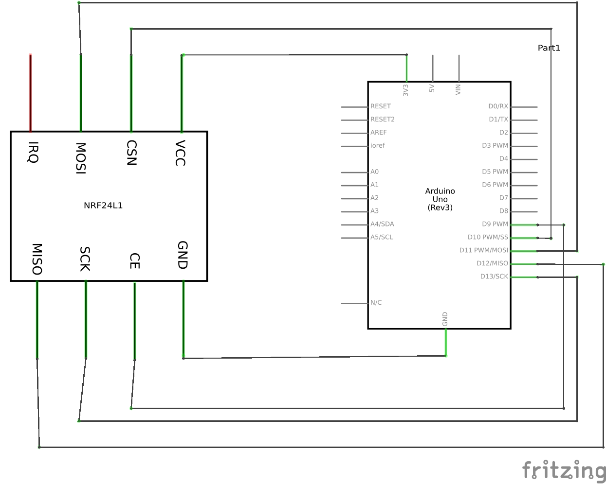
The SPI wires (yellow) have to go exactly to their counterparts:
- MOSI to MOSI
- MISO to MISO
- SCK to SC(L)K
The VCC (red) has to go to any 3.3V pin. Connecting it to 5V pin will damage the nRF24L01.
GRN (black) can go to any ground.
The CSN and CE can go to any pin, however it must correspond to the library constructor. All examples are written assuming:
- CE to pin 9
- CS(N) to pin 10

